

 Call Us Now !
Tel : +86 755 27374946
Call Us Now !
Tel : +86 755 27374946
 Order Online Now !
Email : info@bichengpcb.com
Order Online Now !
Email : info@bichengpcb.com
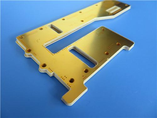
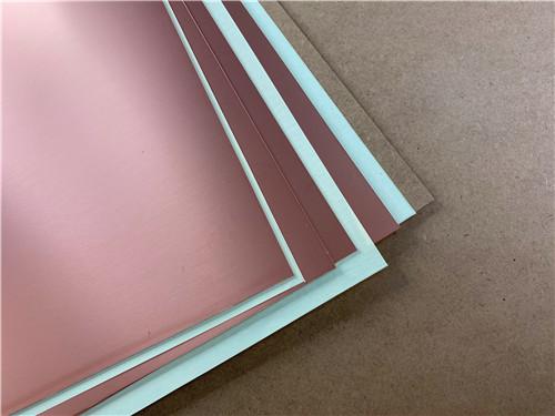
The 2-layer 20mil TMM13i PCB with ENIG finish represents a purpose-built solution for high-frequency applications demanding dielectric stability, low loss, and reliable thermal cycling performance.
Item NO.:
BIC-610v695Order(MOQ):
1-10Payment:
T/TProduct Origin:
ChinaShipping Port:
ShenzhenLead Time:
7-10 days
2-Layer 20mil RogersTMM13i with ENIG Finish High-Frequency Microwave Circuit Board
High-Frequency Microwave Circuit Board — Technical Product Description
This article provides a comprehensive technical overview of a 2-layer rigid PCB fabricated on Rogers TMM13i high-frequency laminate with a 20mil (0.508mm) dielectric core and ENIG surface finish. Part One details the PCB construction, stackup, design statistics, manufacturing standards, and target applications. Part Two offers an in-depth examination of the TMM13i copper-clad laminate (CCL) material, including its complete data sheet, electrical and thermal properties, processing advantages, and standard configurations.
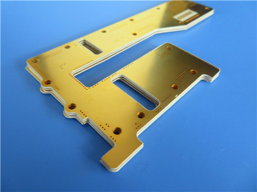
The 2-layer TMM13i PCB is engineered for high-frequency RF and microwave applications where dielectric stability, low insertion loss, and thermal reliability are critical. Built on a 20mil (0.508mm) Rogers TMM13i core with 1 oz (35μm) electrodeposited copper on both outer layers, the board achieves a finished thickness of approximately 0.6mm. The ENIG (Electroless Nickel Immersion Gold) surface finish provides a flat, oxidation-resistant pad surface ideal for fine-pitch SMT assembly and reliable solder joint formation. With board dimensions of 89.65mm × 45.27mm per piece, minimum trace/space of 5/8 mils, and a minimum drilled hole size of 0.25mm, this Rogers PCB balances routing density with manufacturability for RF front-end modules, filters, couplers, and microwave circuitry.
· High-Dk substrate (12.85 ± 0.35) enables compact circuit layouts and smaller antenna geometries
· Isotropic CTE closely matched to copper (19 ppm/K X/Y, 20 ppm/K Z) ensures high plated-through-hole reliability
· Thermoset resin system resists creep and cold flow, supporting reliable wire-bonding
· ENIG finish offers excellent solderability and long shelf life for high-frequency component assembly
· No solder mask on either layer — suitable for applications requiring exposed copper for RF performance
· 100% electrical testing prior to shipment per IPC-Class-2 acceptance standards
The table below summarizes the complete construction specifications of this2-layerRogersTMM13i PCB, from base material through surface finish and quality assurance.
|
Parameter |
Specification |
|
Base Material |
Rogers TMM13i |
|
Layer Count |
2 layers (rigid) |
|
Board Dimensions |
89.65mm × 45.27mm (1 PCS) |
|
Finished Board Thickness |
0.6mm |
|
Finished Copper Weight |
1 oz (1.4 mils / 35μm) outer layers |
|
Via Plating Thickness |
20μm |
|
Minimum Trace / Space |
5 / 8 mils |
|
Minimum Hole Size |
0.25mm |
|
Blind Vias |
None (through-hole only) |
|
Surface Finish |
Immersion Gold (ENIG) |
|
Top Silkscreen |
White |
|
Bottom Silkscreen |
None |
|
Top Solder Mask |
None |
|
Bottom Solder Mask |
None |
|
Electrical Test |
100% tested prior to shipment |
|
Artwork Format |
Gerber RS-274-X |
|
Acceptance Standard |
IPC-Class-2 |
|
Availability |
Worldwide |
The stackup employs a symmetric two-layer structure with a 20mil TMM13i dielectric core sandwiched between two 35μm electrodeposited copper layers, yielding a nominal finished thickness of approximately 0.6mm (35μm + 508μm + 35μm = 578μm).
|
Layer |
Material |
Thickness |
|
Copper Layer 1 (Top) |
Electrodeposited Copper (1 oz) |
35μm (1.4 mils) |
|
Core (Dielectric) |
Rogers TMM13i Substrate |
20 mils (0.508mm) |
|
Copper Layer 2 (Bottom) |
Electrodeposited Copper (1 oz) |
35μm (1.4 mils) |
The design statistics reflect a moderately dense RF circuit with 32 components and 38 vias distributed across just two signal nets, typical of dedicated high-frequency function modules.
|
Metric |
Count |
|
Components |
32 |
|
Total Pads |
54 |
|
Through-Hole Pads |
29 |
|
Top SMT Pads |
26 |
|
Bottom SMT Pads |
0 |
|
Vias |
38 |
|
Nets |
2 |
This Rogers TMM PCB is manufactured to IPC-Class-2 acceptance standards, with 100% electrical testing performed before shipment. The TMM13i materialis fully compatible with standard PCB fabrication processes — it does not require sodium napthanate treatment prior to electroless plating, and its thermoset resin system resists process chemicals, reducing the risk of damage during fabrication and assembly. The material is lead-free process compatible and rated UL 94V-0 for flammability. The ENIG surface finish typically deposits 2–5μm nickel with 0.05–0.15μm gold, providing a reliable intermetallic foundation for solder assembly and an extended shelf life.
The 2-layer 20mil TMM13i PCB with ENIG finish represents a purpose-built solution for high-frequency applications demanding dielectric stability, low loss, and reliable thermal cycling performance. Its symmetric stackup, copper-matched CTE, and thermoset resin foundation address the key failure modes common in PTFE-based microwave boards — pad lifting, via fatigue, and cold flow — while the ENIG finish ensures assembly readiness. With IPC-Class-2 quality assurance and 100% electrical testing, thisTMM13ihigh frequencyPCB offers a dependable platform for RF filters, couplers, antennas, and microwave subsystems where material performance directly translates to system-level signal integrity.
Rogers TMM13i is an isotropic thermoset microwave material — a ceramic-filled hydrocarbon thermoset polymer composite engineered specifically for high-reliability plated-through-hole stripline and microstrip applications. TMM13i occupies the high-dielectric-constant tier of the TMM family, with a process Dk of 12.85 ± 0.35 at 10 GHz, making it suitable for designs where circuit miniaturization and controlled impedance in compact geometries are priorities. The material combines the electrical performance benefits of ceramic substrates with the processing convenience of soft organic substrates, eliminating the need for specialized fabrication techniques associated with pure ceramic or PTFE laminates.
TMM13i is composed of a ceramic filler dispersed within a hydrocarbon thermoset polymer matrix. Unlike PTFE-based microwave materials, TMM13i uses a thermoset resin that does not soften or reflow when heated — a property that enables reliable wire-bonding of component leads directly to circuit traces without risk of pad lifting or substrate deformation. The ceramic loading provides the high dielectric constant and low thermal coefficient of Dk, while the hydrocarbon polymer matrix contributes mechanical toughness and chemical resistance. The material is available clad with electrodeposited copper foil ranging from 1/2 oz (18μm) to 2 oz (70μm), or bonded directly to brass or aluminum plates for enhanced heat spreading.
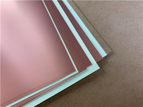
Figure 1: Rogers TMM13i high-frequency laminate material
The following table presents the complete electrical, thermal, and mechanical property data for TMM13i as specified in the Rogers official data sheet, including test conditions and reference standards.
|
Property |
Value |
Direction |
Units |
Conditions |
Test Method |
|
Dielectric Constant (process) |
12.85 ± 0.35 |
Z |
— |
10 GHz |
IPC-TM-650 2.5.5.5 |
|
Dielectric Constant (design) |
12.2 |
— |
— |
8–40 GHz |
Diff. Phase Length |
|
Dissipation Factor (process) |
0.0019 |
Z |
— |
10 GHz |
IPC-TM-650 2.5.5.5 |
|
Thermal Coeff. of Dk |
-70 |
— |
ppm/°K |
-55 to +125°C |
IPC-TM-650 2.5.5.5 |
|
Insulation Resistance |
>2000 |
— |
GΩ |
C/96/60/95 |
ASTM D257 |
|
Electrical Strength |
213 |
Z |
V/mil |
— |
IPC-TM-650 2.5.6.2 |
|
Decomposition Temp. (Td) |
425 |
— |
°C |
TGA |
ASTM D3850 |
|
CTE – X axis |
19 |
X |
ppm/K |
0–140°C |
ASTM E831 / IPC 2.4.41 |
|
CTE – Y axis |
19 |
Y |
ppm/K |
0–140°C |
ASTM E831 / IPC 2.4.41 |
|
CTE – Z axis |
20 |
Z |
ppm/K |
0–140°C |
ASTM E831 / IPC 2.4.41 |
|
Cu Peel Strength (after stress) |
4.0 (0.7) |
X,Y |
lb/in (N/mm) |
Solder float, 1oz EDC |
IPC-TM-650 2.4.8 |
|
Moisture Absorption (1.27mm) |
0.16 |
— |
% |
D/24/23 |
ASTM D570 |
|
Moisture Absorption (3.18mm) |
0.13 |
— |
% |
D/24/23 |
ASTM D570 |
|
Specific Gravity |
3.0 |
— |
— |
As received |
ASTM D792 |
|
Lead-Free Process Compatible |
YES |
— |
— |
— |
— |
TMM13i's process dielectric constant of 12.85 ± 0.35 (measured at 10 GHz via IPC-TM-650 method 2.5.5.5) is among the highest in the TMM product line. For design purposes, Rogers recommends a design Dk of 12.2 across the 8–40 GHz range, determined by the Differential Phase Length Method. The dissipation factor is 0.0019 at 10 GHz, contributing to low insertion loss in high-frequency transmission lines. The thermal coefficient of dielectric constant is -70 ppm/°K over -55°C to +125°C, ensuring that impedance and resonant frequency remain stable across wide operating temperature ranges — a critical parameter for filters and oscillators in aerospace and outdoor communications equipment. The material exhibits an electrical strength of 213 V/mil and insulation resistance exceeding 2000 GΩ under C/96/60/95 conditions, providing robust isolation for high-voltage RF circuits.
The decomposition temperature (Td) of TMM13i is 425°C (measured by TGA per ASTM D3850), well above standard lead-free reflow profiles (typically 245–260°C peak), ensuring thermal stability during assembly. The coefficients of thermal expansion are nearly isotropic and closely matched to copper: 19 ppm/K in both X and Y axes, and 20 ppm/K in the Z axis (0–140°C, ASTM E831 / IPC-TM-650 2.4.41). This close CTE match to copper (≈17 ppm/K) minimizes shear stress at the copper-dielectric interface during thermal cycling, directly improving plated-through-hole reliability — a key differentiator versus PTFE laminates, which typically exhibit higher Z-axis CTE and greater via fatigue risk. Copper peel strength after thermal stress (solder float, 1 oz EDC) is 4.0 lb/inch (0.7 N/mm), confirming robust copper adhesion even after thermal excursion. Moisture absorption is low at 0.16% for 1.27mm thickness and 0.13% for 3.18mm thickness (ASTM D570, D/24/23), minimizing dielectric drift in humid environments. The specific gravity is 3.0, reflecting the high ceramic filler content.
TMM13i offers several fabrication advantages over competing high-frequency materials.
Rogers TMM13i occupies a distinctive position in the high-frequency laminate market: it delivers a high dielectric constant (12.85) with the mechanical robustness and processing simplicity of a thermoset composite, bridging the performance gap between ceramic substrates and PTFE microwave laminates. Its copper-matched CTE, 425°C decomposition temperature, low moisture absorption, and absence of specialized plating requirements make it a manufacturable and reliable choice for high-frequency circuits operating in thermally demanding environments. Whether used for compact patch antennas, high-Q filters, or satellite communication subsystems, TMM13i provides a stable dielectric platform where signal integrity and long-term reliability are non-negotiable.





Previous:
2-Layer 100mil Rogers TMM3 Custom High Frequency PCB with EPIG Surface FinishNext:
Rogers TMM10i PCB 30mil ENIG 2-layer Black Solder Mask with Edge PlatingIf you have questions or suggestions,please leave us a message,we will reply you as soon as we can!
Categories
New Products

Wangling F4BTMS220 2-Layer DK2.2 PCB 10 mil Core with Immersion Gold

Wangling F4BTME350 10mil DK3.5 High Frequency Substrate PCB 2-Layer Immersion Gold

Wangling F4BTM300 Custom 2-layer PCB 20mil DK3.0 Substrate with Immersion Gold

Rogers 20mil RT/duroid 6202 2-layer ENIG High-Frequency Microwave PCB

Rogers 20mil AD250C PCB Pure Gold High-Frequency Antenna Circuit Board

8-Layer Hybrid RF PCB: RO4350B + TG170 FR-4 + RO4003C with RO4450F Bondply

4-Layer Rogers RO3010 Hybrid PCB Immersion Silver 2.8mm Finished Thickness

4-Layer 20mil Rogers RO3210 ISIG High-Frequency PCB with Controlled Depth Milling
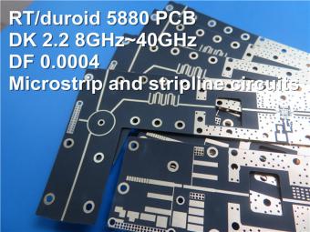
This is a type of double sided RF PCB built on RT/duroid 5880 for the application of Radar Systems.
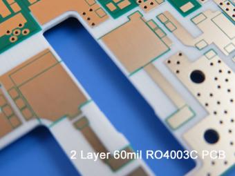
RO4003C PCBs are hydrocarbon ceramic filled laminates, not PTFE which are designed to offer superior high frequency performance.
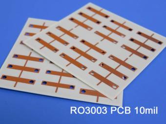
Rogers RO3003 high frequency circuit materials are ceramic-filled PTFE composites intended for use in commercial microwave and RF applications. It was designed to offer exceptional electrical and mechanical stability at competitive prices.
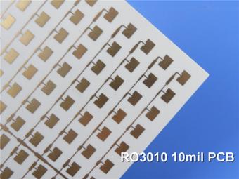
RO3010 laminates are competitively priced products with exceptional mechanical and electrical stability. This stability simplifies the design of broadband components and allows the materials to be used in a wide range of applications over a very broad range of frequencies.
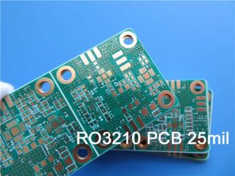
These RO3210 materials are engineered to offer exceptional electrical performance and mechanical stability. RO3210 laminates combine the surface smoothness of a non-woven PTFE laminate.
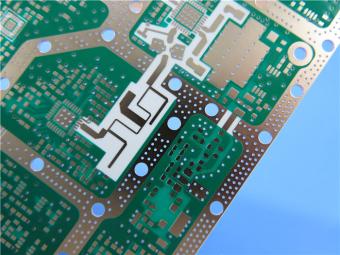
RT/duroid 6035HTC laminates are an exceptional choice for high power applications.
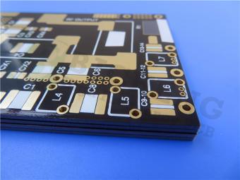
TC350 is designed to provide enhanced heat-transfer through “Best-In-Class” thermal conductivity, while reducing dielectric loss and insertion loss. Lower losses result in higher Amplifier and Antenna Gains/Efficiencies.
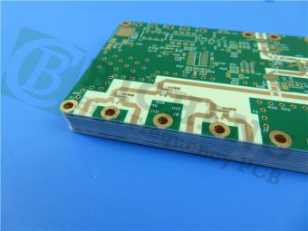
RO3035 materials exhibit a coefficient of thermal expansion(CTE) in the X and Y axis of 17 ppm/℃. This expansion coefficient is matched to that of copper, which allows the material to exhibit excellent dimensional stability.
 6-11C Shidai Jingyuan, Fuyong, Baoan, Shenzhen, Guangdong, China 518103


For inquiries about our products or pricelist, please leave to us and we will be in touch within 24 hours.
© Copyright: 2026 Shenzhen Bicheng Electronics Technology Co., Ltd.. All Rights Reserved.

IPv6 network supported


