

 Call Us Now !
Tel : +86 755 27374946
Call Us Now !
Tel : +86 755 27374946
 Order Online Now !
Email : info@bichengpcb.com
Order Online Now !
Email : info@bichengpcb.com
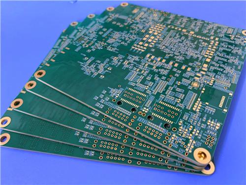
This 14-layer M6 high-speed ENEPIG PCB combines a proven low-loss laminate, a symmetric impedance-optimised stackup, and Class 3 build standards into a reliable platform for next-generation high-frequency electronics.
Item NO.:
BIC-609-v694Order(MOQ):
1-10Payment:
T/TProduct Origin:
ChinaShipping Port:
ShenzhenLead Time:
7-10 days
14-Layer Megtron6 (M6) High-Speed PCB 2.123mmwith ENEPIG Surface Finish Impedance Control
This14-layer high-speed PCB is built on Panasonic Megtron 6 (M6) R-5775(G) laminate, a low-Dk glass-cloth material engineered for multi-gigabit signal transmission. With a pressed thickness of 2.123 mm and uniform 1 oz copper on all fourteen layers, it balances signal integrity, thermal dissipation, and mechanical rigidity. The ENEPIG surface finish, 25 µm via plating, and IPC-6012 Class 3 compliance target high-reliability segments including 5G infrastructure, high-speed computing servers, automotive ADAS, and test & measurement equipment.
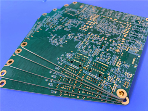
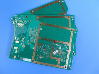
Figure 1. 14-Layer M6 High-Speed PCB (ENEPIG)
The table below summarises the core construction parameters of this 14-layer M6 board, covering material selection, dimensional tolerances, surface finish, and quality acceptance criteria.
|
Parameter |
Specification |
|
Base Material |
Panasonic Megtron 6 (M6) R-5775(G) |
|
Layer Count |
14 layers |
|
Board Dimensions |
100 mm × 98 mm = 1 PCS |
|
Finished Board Thickness |
2.123 mm |
|
Finished Cu Weight (all layers) |
1 oz (35 µm) |
|
Via Plating Thickness |
25 µm |
|
Surface Finish |
ENEPIG (Electroless Ni / Electroless Pd / Immersion Au) |
|
Top Solder Mask |
Green |
|
Bottom Solder Mask |
Green |
|
Top Silkscreen |
White |
|
Bottom Silkscreen |
White |
|
Impedance Control |
Required |
|
Via Construction |
Vias < 0.4 mm: resin-plugged and copper-plated filled |
|
Quality Standard |
IPC-6012 Class 3 |
|
Electrical Test |
100 % electrical test prior to shipment |
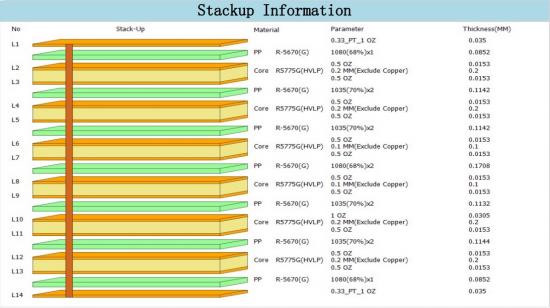
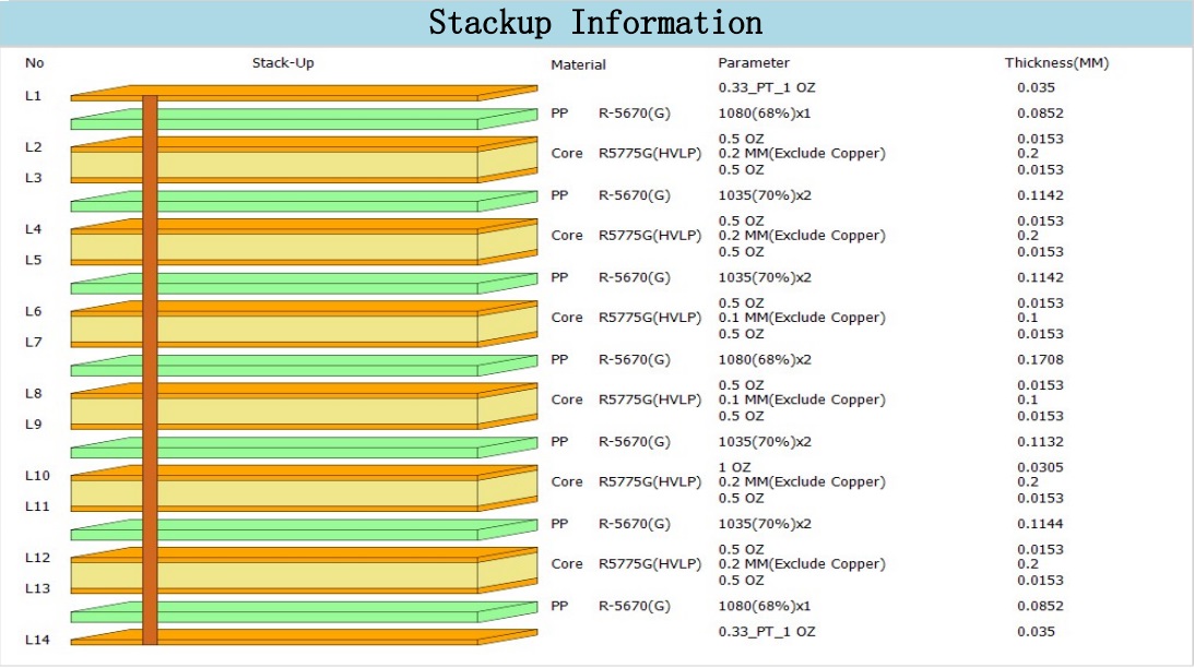
The14-layer symmetric stackupuses six R-5775(G) cores interleaved with seven R-5670(G) prepreg layers. Outer-layer prepreg (1078 glass, 70 % resin content, 89 µm) is selected for controlled-impedance microstrip routing, while 1035 prepreg (60 µm) fills inner layer gaps. The total calculated thickness is 2.124 mm, matching the 2.123 mm target within normal lamination tolerance.
Unlike conventional ENIG, ENEPIG deposits an electroless palladium layer between nickel and gold. This barrier prevents nickel corrosion ("black pad") and supports both lead-free solder reflow and gold/aluminium wire bonding on the same pad. The finish survives multiple reflow cycles, suiting high-density BGA and QFN assemblies.
All vias below 0.4 mm are resin-plugged and copper-plated flat (via-in-pad). This yields a coplanar pad surface that eliminates solder wicking, enables 0.4 mm pitch BGA mounting, and improves thermal conduction. It also reduces trapped-void defects that cause intermittent opens under thermal cycling.
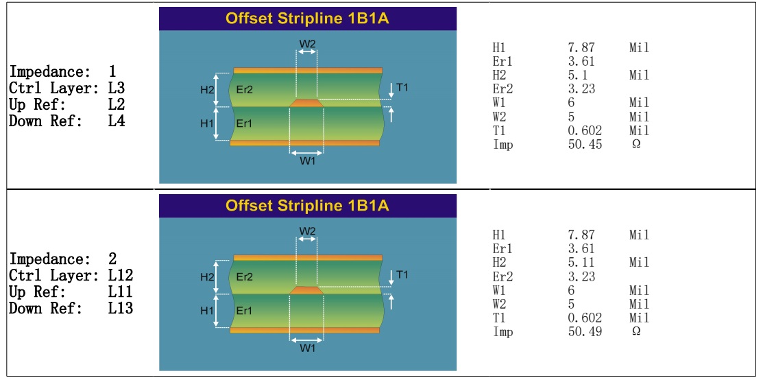
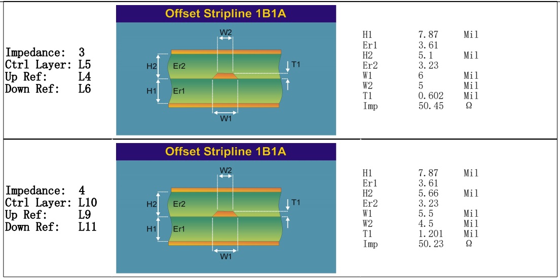
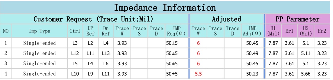
Built to IPC-6012 Class 3 — the highest rigid-PCB performance class — this board requires minimum 25 µm via copper plating, stricter dimensional tolerances, and enhanced thermal qualification. Class 3 is mandated for aerospace, medical life-support, and automotive safety-critical electronics.
• 5G / 6G base station power-amplifier and beamforming controllers
• High-speed server and switch backplanes (25 Gbps – 112 Gbps SerDes)
• Automotive radar and ADAS domain controllers
• High-end test & measurement and oscilloscope front-ends
• Aerospace & defence avionics modules
• Optical transceiver and coherent DSP carrier cards
This 14-layer M6 high-speed ENEPIG PCB combines a proven low-loss laminate, a symmetric impedance-optimised stackup, and Class 3 build standards into a reliable platform for next-generation high-frequency electronics. ENEPIG and resin-plugged vias address the assembly demands of fine-pitch high-I/O packages, while uniform 1 oz copper and 2.123 mm thickness ensure solid power delivery and mechanical stiffness. For multi-gigabit designs in harsh or safety-critical environments, this construction offers a well-documented, data-supported solution.
Part 2: CCL Material Knowledge — Megtron 6 (R-5775(G)
Megtron 6 (M6) is Panasonic's sixth-generation high-speed, low-loss multi-layer laminate system, comprising R-5775(G) copper-clad laminate and R-5670(G) prepreg. The "(G)" designation indicates the low-Dk glass-cloth version, which further reduces effective dielectric constant versus the standard glass variant. M6 belongs to the PPE (polyphenylene ether) modified epoxy resin family, engineered to deliver consistently low Dk and ultra-low Df across a wide frequency range from 1 GHz through 58 GHz — a performance envelope that conventional FR-4 (Df ≈ 0.020 at 1 GHz) cannot approach.
The following table presents the full thermal, electrical, and physical property datasheet for R-5775(G) laminate as published by Panasonic. All values are typical; sample thickness is 0.750 mm (Core Type 30).
|
Property |
Units |
Test Method |
Condition |
Typical Value |
|
Glass Transition Temp (Tg) |
°C |
DSC |
As received |
185 |
|
Glass Transition Temp (Tg) |
°C |
DMA |
As received |
210 |
|
Thermal Decomposition Temp (Td) |
°C |
TGA |
As received |
410 |
|
Time to Delaminate (T288) — without Cu |
min |
IPC TM-650 2.4.24.1 |
As received |
> 120 |
|
Time to Delaminate (T288) — with Cu |
min |
IPC TM-650 2.4.24.1 |
As received |
> 120 |
|
CTE α1 — X axis |
ppm/°C |
IPC TM-650 2.4.24 |
< Tg |
14 – 16 |
|
CTE α1 — Y axis |
ppm/°C |
IPC TM-650 2.4.24 |
< Tg |
14 – 16 |
|
CTE α1 — Z axis |
ppm/°C |
IPC TM-650 2.4.24 |
< Tg |
45 |
|
CTE α2 — Z axis |
ppm/°C |
IPC TM-650 2.4.24 |
> Tg |
260 |
|
Volume Resistivity |
MΩ·cm |
IPC TM-650 2.5.17.1 |
C-96/35/90 |
1 × 10⁹ |
|
Surface Resistivity |
MΩ |
IPC TM-650 2.5.17.1 |
C-96/35/90 |
1 × 10⁸ |
|
Dielectric Constant (Dk) |
— |
IPC TM-650 2.5.5.9 |
@ 1 GHz, C-24/23/50 |
3.40 |
|
Dielectric Constant (Dk) |
— |
IEC 63185 (2020) |
@ 13 GHz |
3.34 |
|
Dissipation Factor (Df) |
— |
IPC TM-650 2.5.5.9 |
@ 1 GHz, C-24/23/50 |
0.002 |
|
Dissipation Factor (Df) |
— |
IEC 63185 (2020) |
@ 13 GHz |
0.0037 |
|
Water Absorption |
% |
IPC TM-650 2.6.2.1 |
D-24/23 |
0.14 |
|
Peel Strength (1 oz H-VLP) |
kN/m |
IPC TM-650 2.4.8 |
As received |
0.8 |
|
Flammability |
— |
UL 94 |
C-48/23/50 |
V-0 |
R-5775(G) is available in multiple core thicknesses and glass-cloth constructions. Dk is measured at 1 GHz per IPC TM-650 2.5.5.9 and at 13–58 GHz per the balanced-type circular disk resonance method (IEC 63185). Higher resin-content cores (e.g. 1035 cloth, 67–70 % RC) exhibit lower Dk (~3.16–3.25), while standard 2013/2116 cores (56 % RC) sit at 3.34–3.40.
|
Core Type |
Thickness (mm) |
Cloth Style |
Ply |
Resin % |
Dk 1G |
Dk 13G |
Dk 58G |
|
2 |
0.050 |
1035 |
1 |
67 |
3.25 |
3.19 |
3.19 |
|
3 |
0.075 |
1078 |
1 |
65 |
3.28 |
3.22 |
3.22 |
|
4 |
0.100 |
2013 |
1 |
56 |
3.40 |
3.34 |
3.34 |
|
5 |
0.127 |
1078 |
2 |
59 |
3.37 |
3.29 |
3.29 |
|
7 |
0.178 |
1078 |
2 |
70 |
3.22 |
3.16 |
3.16 |
|
8 |
0.200 |
2013 |
2 |
56 |
3.40 |
3.34 |
3.34 |
|
10 |
0.250 |
2116 |
2 |
56 |
3.40 |
3.34 |
3.34 |
|
12 |
0.300 |
2013 |
3 |
56 |
3.40 |
3.34 |
3.34 |
|
16 |
0.400 |
2013 |
4 |
56 |
3.40 |
3.34 |
3.34 |
|
20 |
0.500 |
2116 |
4 |
56 |
3.40 |
3.34 |
3.34 |
|
30 |
0.750 |
2116 |
6 |
56 |
3.40 |
3.34 |
3.34 |
R-5670(G) prepregis the matching bonding sheet for R-5775(G) cores. Resin content directly controls both cured thickness and effective Dk: higher resin content yields thinner, lower-Dk prepreg. The 1078 style at 70 % RC (89 µm cured) is widely used for outer-layer impedance control, while 1035 at 72 % RC (60 µm) serves thin inner-layer gaps.
|
ClothStyle |
Resin Content (%) |
Cured Thickness (µm) |
Dk 1G |
Df 1G |
Df 13G |
|
1035 |
72 |
60 |
3.20 |
0.002 |
0.0037 |
|
1035 |
75 |
68 |
3.16 |
0.002 |
0.0037 |
|
1035 |
77 |
74 |
3.13 |
0.002 |
0.0037 |
|
1078 |
66 |
77 |
3.26 |
0.002 |
0.0037 |
|
1078 |
70 |
89 |
3.22 |
0.002 |
0.0037 |
|
1078 |
74 |
104 |
3.17 |
0.002 |
0.0037 |
|
1078 |
77 |
118 |
3.13 |
0.002 |
0.0037 |
|
2013 |
56 |
98 |
3.40 |
0.002 |
0.0037 |
|
2116 |
56 |
125 |
3.40 |
0.002 |
0.0037 |
The defining advantage of M6 over FR-4 is its dissipation factor. At 1 GHz, R-5775(G) shows Df = 0.002 — roughly one-tenth of standard FR-4 (~0.020). At 13 GHz Df rises only to 0.0037, and even at 58 GHz it stays below 0.0046. Since dielectric loss scales linearly with Df, this low, flat Df cuts channel loss at multi-gigabit rates. For a 20-inch stripline at 13 GHz, M6 can reduce dielectric loss by 1.5–2 dB versus mid-loss FR-4, improving eye opening and reducing reliance on equalisation or re-timers.
Dk is equally stable, dropping only 0.06 (3.40 to 3.34) from 1 GHz to 13 GHz and remaining flat to 58 GHz. This near-frequency-independent Dk minimises phase distortion and group-delay variation — critical for 64-QAM and PAM-4 used in 56G/112G SerDes and coherent optical modules.
R-5775(G) delivers a DSC Tg of 185 °C and DMA Tg of 210 °C, well above the 130–140 °C of standard FR-4. Td of 410 °C and T288 time-to-delamination over 120 minutes (with and without copper) confirm robust resistance to repeated 260 °C lead-free reflow. In-plane CTE of 14–16 ppm/°C closely matches copper (17 ppm/°C), reducing registration shift and PTH fatigue; Z-axis CTE of 45 ppm/°C below Tg also favours via reliability in thick high-layer-count boards.
Per Panasonic's guideline, M6 lamination uses peak product temperature above 185 °C for 75 minutes at 3.0–4.0 MPa, with a 2.0–4.0 °C/min heat-up rate. Because R-5775(G) has lower permanganate desmear weight loss (0.2–0.4) than FR-4 (1.0), roughly twice the FR-4 desmear time is recommended; plasma desmear uses half the FR-4 time. Drilling targets 100–150 m/min peripheral velocity with high-helix bits and lubricated entry material. A pre-bake (e.g. 5 h at 150 °C) before nickel plating is advised for ENIG/ENEPIG.
Megtron 6 R-5775(G) is a mature, well-characterised high-speed laminate with electrical, thermal, and mechanical data fully documented across 1–58 GHz. Its ultra-low flat Df (0.002 @ 1 GHz, <0.0046 @ 58 GHz), stable Dk (3.34–3.40), and 185 °C Tg make it a defensible choice for 25 Gbps+ boards. Paired with R-5670(G) prepreg and processed within published windows, M6 delivers repeatable impedance and reliability. The datasheet figures above give designers a concrete basis for loss-budget and reliability modelling when upgrading from FR-4 or mid-loss materials.





If you have questions or suggestions,please leave us a message,we will reply you as soon as we can!
Categories
New Products

Wangling F4BTMS220 2-Layer DK2.2 PCB 10 mil Core with Immersion Gold

Wangling F4BTME350 10mil DK3.5 High Frequency Substrate PCB 2-Layer Immersion Gold

Wangling F4BTM300 Custom 2-layer PCB 20mil DK3.0 Substrate with Immersion Gold

Rogers 20mil RT/duroid 6202 2-layer ENIG High-Frequency Microwave PCB

Rogers 20mil AD250C PCB Pure Gold High-Frequency Antenna Circuit Board

8-Layer Hybrid RF PCB: RO4350B + TG170 FR-4 + RO4003C with RO4450F Bondply

4-Layer Rogers RO3010 Hybrid PCB Immersion Silver 2.8mm Finished Thickness

4-Layer 20mil Rogers RO3210 ISIG High-Frequency PCB with Controlled Depth Milling
Base material: RO4350B 0.508 mm + FR4 0.6mm + PP 0.306mm
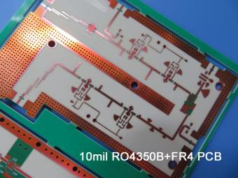
It’s for the application of 2.4 Ghz Antenna. It's 1.0 mm thick with through holes. Green solder mask covers both sides and immersion gold on pads.
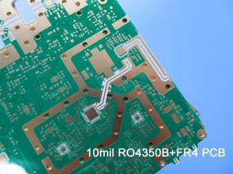
This type is more complex. The 10mil RO4350B core is the same. The main difference is that it contains 3 types blind via.
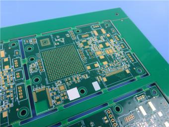
This is a type of 14-layer HDI printed circuit board built on FR-4 Tg170 substrate for the application of codec equipment.
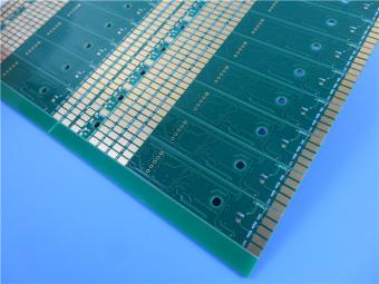
This is a type of High-Tg 4-layer PCB Built on TU-768 material. Each layer is plated with 1oz copper.
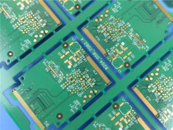
ThunderClad 2 ( TU-883 ) is a very low loss category material based on a high performance resin.
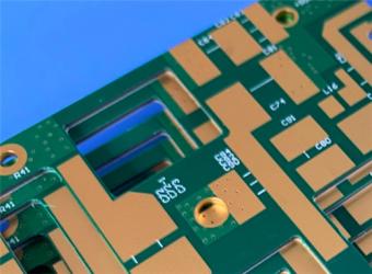
TU-872 SLK copper clad laminate stands out as a high-performance material solution for advancedmultilayer PCBs.
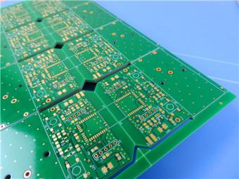
This 12-layer TG200 FR4 PCB is not just a component; it is a carefully engineered platform for high-performance electronics. Its construction combines a sophisticated stackup, advanced via technology, and precision impedance control to create a solution that meets the rigorous demands of modern high-speed digital and telecommunications systems.
 6-11C Shidai Jingyuan, Fuyong, Baoan, Shenzhen, Guangdong, China 518103


For inquiries about our products or pricelist, please leave to us and we will be in touch within 24 hours.
© Copyright: 2026 Shenzhen Bicheng Electronics Technology Co., Ltd.. All Rights Reserved.

IPv6 network supported


