

 Call Us Now !
Tel : +86 755 27374946
Call Us Now !
Tel : +86 755 27374946
 Order Online Now !
Email : info@bichengpcb.com
Order Online Now !
Email : info@bichengpcb.com
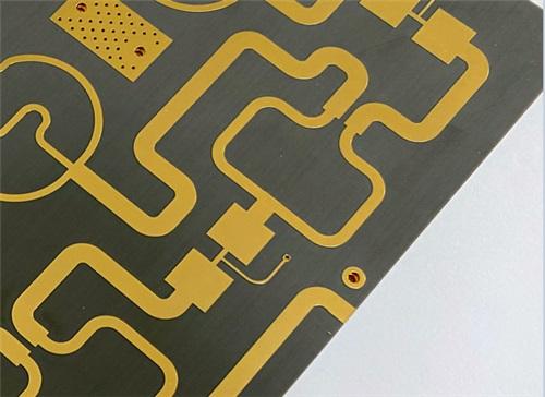
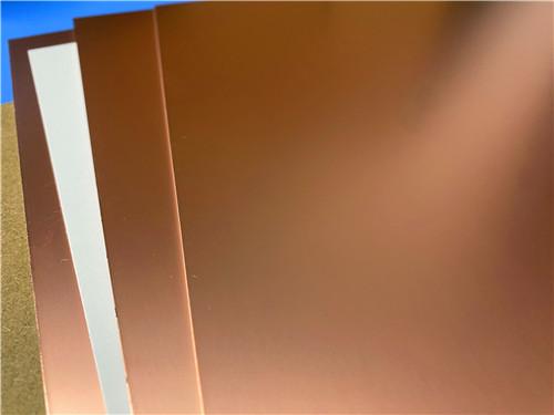
This custom 7.5mil TLY-52-layer EPIG PCB delivers a purpose-built ultra-thin high-frequency circuit platform optimized for millimeter-wave RF applications.
Item NO.:
BIC-597-v682.0Order(MOQ):
1-10Payment:
T/TProduct Origin:
ChinaShipping Port:
ShenzhenLead Time:
7-10 days
7.5mil AGC TaconicTLY-5 Substrate Custom PCB EPIG Finish Bare Copper
Executive Summary
This presentation delivers a comprehensive, differentiated technical profile of a custom 2-layer rigid microwave PCB fabricated on 7.5mil AGC TLY-5 high-frequency PTFE composite substrate with EPIG electroplated immersion gold surface finish. Designed for millimeter-wave radar, satellite communication and aerospace phased array hardware, the Taconic TLY-5 DK2.2 PCB adheres to IPC-Class-2 reliability standards with zero solder mask, zero silkscreen ultra-clean bare copper construction, tight dimensional tolerances and fully validated electrical performance.
The content is split into two distinct standalone modules: complete PCB hardware specification and in-depth TLY-5 CCL core substrate technical breakdown, with structured data tables, performance differentiation analysis, application mapping and conclusive technical takeaways for design, procurement and manufacturing stakeholders.
Part 1: Complete PCB Product Specification & Hardware Profile
1.1 PCB Construction Details Overview
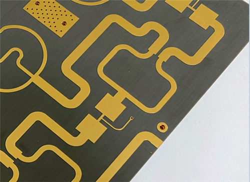
This section tabulates all mechanical, surface treatment, fabrication and test rules governing the finished 45mmx 87mm single-piece Taconic TLY-5 PCB, covering dimensional control, trace/hole limits, copper weight, plating, surface finish and mandatory factory electrical validation.
|
Parameter |
Specification |
|
Board Size |
45mm × 87mm, ±0.15mm tolerance |
|
Min. Trace / Space |
6mil / 10mil |
|
Min. Mechanical Hole |
0.4mm (through-hole only) |
|
Board Thickness |
0.3mm (7.5mil TLY-5 core + dual 35μm copper) |
|
Outer Copper Weight |
1oz (35μm finished) |
|
Via Plating |
20μm copper barrel |
|
Surface Finish |
EPIG (Electroplated Immersion Gold) |
|
Solder Mask |
None (both sides, bare copper) |
|
Silkscreen |
None (both sides) |
|
Quality Standard |
IPC-Class-2, 100% electrical test |
1.2 PCB Stackup Architecture Overview
This table outlines the symmetrical two-layer rigid laminate stackup, defining each conductive copper layer and central TLY-5 dielectric core with exact thickness values for RF impedance calculation.
|
Layer |
Material |
Thickness |
|
L1 (Top) |
Copper Foil |
35μm (1oz) |
|
Core |
AGC TLY-5 CCL |
0.191mm (7.5mil) |
|
L2 (Bottom) |
Copper Foil |
35μm (1oz) |
1.3 PCB Component & Circuit Statistics Overview
This table quantifies all circuit features, component footprints, pad types, vias and electrical nets to quantify circuit density and manufacturing complexity for high-volume production planning.
|
Item |
Quantity |
|
Components |
37 pcs |
|
Total Pads |
149 (85 through-hole + 64 top SMT) |
|
Through Vias |
139 pcs |
|
Electrical Nets |
2 nets |
Conclusion for PCB Hardware Module
This custom 7.5mil TLY-5 2-layer EPIG PCB delivers a purpose-built ultra-thin high-frequency circuit platform optimized for millimeter-wave RF applications. Its core differentiators include mask/silkscreen-free bare copper construction, tightly controlled 7.5mil low-loss TLY-5 dielectric core, symmetrical dual 35μm copper stack, full through-via architecture, EPIG corrosion-resistant surface finish and IPC-Class-2 validated manufacturing. The balanced circuit density, minimal net count and 100% electrical pre-ship testing guarantee consistent RF performance, high manufacturing yield and global production scalability, making it a cost-effective alternative to complex multi-layer PTFE PCBs for automotive radar, satellite communication and aerospace mmWave subsystem designs.
Part 2: In-Depth Technical Breakdown of TLY-5 Core CCL Substrate
2.1 TLY-5 Material Core Introduction & Differentiation
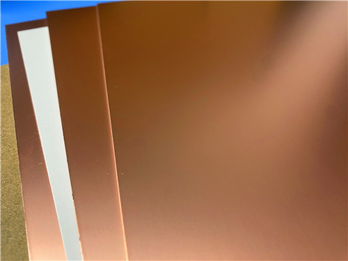
AGC TLY-5 is an avionics and aerospace-grade woven lightweight fiberglass-reinforced PTFE copper clad laminate, engineered to outperform chopped-fiber PTFE composite substrates in dimensional stability and mass-production yield while retaining ultra-low high-frequency signal loss. Unlike discontinuous chopped fiber PTFE materials that suffer inconsistent dielectric uniformity and high thermal expansion variation, TLY-5’s continuous woven glass matrix delivers superior mechanical rigidity and predictable DK/Df across all operating frequencies from 10GHz up to 77GHz automotive radar and Ka/E/W band satellite hardware.
Independent OEM 77GHz insertion loss testing confirms TLY-5 matches the RF electrical performance of competing chopped-fiber PTFE laminates, with a dramatic uplift in production yield–a critical commercial differentiation for high-volume automotive radar manufacturing. The material supports laser ablation via formation, compatible with fine-line 6/10mil trace routing specified on the matching PCB hardware, and is available in incremental thickness steps starting at 7.5mil (0.191mm), the exact dielectric core selected for this PCB design.
2.2 Full TLY-5 CCL Datasheet Property Table
This consolidated datasheet compiles all electrical, thermal, mechanical, chemical and safety performance metrics with standardized industry test methods for cross-substrate comparison.
Table: Complete AGC TLY-5 CCL Material Property Datasheet
|
Property Classification |
Test Parameter |
Test Condition |
Typical Value |
Unit |
Standard Test Method |
|
Electrical Properties |
Dielectric Constant (Dk) |
10GHz, 23°C |
2.2 |
- |
IPC-650 2.5.5.5 |
|
Dissipation Factor (Df / Loss Tangent) |
10GHz, 23°C |
0.0009 |
- |
IPC-650 2.5.5.5 |
|
|
Volume Resistivity |
Post Elevated Temperature |
10¹⁰ |
Mohms/cm |
IPC-650 2.5.17.1 |
|
|
Volume Resistivity |
Post Humidity Exposure |
10¹⁰ |
Mohms/cm |
IPC-650 2.5.17.1 |
|
|
Surface Resistivity |
Post Elevated Temperature |
10⁸ |
Mohms |
IPC-650 2.5.17.1 |
|
|
Surface Resistivity |
Post Humidity Exposure |
10⁸ |
Mohms |
IPC-650 2.5.17.1 |
|
|
Thermal Properties |
Thermal Conductivity |
Room Temperature |
0.22 |
W/M*K |
ASTM F 433 |
|
CTE X-Axis (25–260°C) |
Thermal Mechanical Analysis |
26 |
ppm/°C |
ASTM D 3386 (TMA) |
|
|
CTE Y-Axis (25–260°C) |
Thermal Mechanical Analysis |
15 |
ppm/°C |
ASTM D 3386 (TMA) |
|
|
CTE Z-Axis (25–260°C) |
Thermal Mechanical Analysis |
217 |
ppm/°C |
ASTM D 3386 (TMA) |
|
|
Mechanical Properties |
Copper Peel Strength (1oz C1 Copper) |
Standard Ambient |
3.04 (17) |
N/mm (lbs/in) |
IPC-650 2.4.8 |
|
Copper Peel Strength (1oz CL1 Copper) |
Standard Ambient |
2.86 (16) |
N/mm (lbs/in) |
IPC-650 2.4.8 |
|
|
Copper Peel Strength (1/2oz ED Copper) |
Standard Ambient |
1.96 (11) |
N/mm (lbs/in) |
IPC-650 2.4.8 |
|
|
Copper Peel Strength (1oz CL1 Copper) |
Elevated Temperature |
2.32 (13) |
N/mm (lbs/in) |
IPC-650 2.4.8 |
|
|
Flexural Strength (MD Machine Direction) |
Ambient |
96.91 (14,057) |
N/mm² (psi) |
IPC-650 2.4.4 |
|
|
Flexural Strength (CD Cross Direction) |
Ambient |
89.32 (12,955) |
N/mm² (psi) |
IPC-650 2.4.4 |
|
|
Young’s Modulus (MD) |
Ambient |
9.65 × 10³ (1.4 × 10⁶) |
N/mm² (psi) |
ASTM D 3039 / IPC-650 2.4.19 |
|
|
Poisson’s Ratio (MD) |
Ambient |
0.21 |
- |
ASTM D 3039 / IPC-650 2.4.19 |
|
|
Specific Gravity (Density) |
Ambient |
2.19 |
g/cm³ |
ASTM D 792 |
|
|
Dimensional Stability (MD, 10mil Core) |
Post Bake & Thermal Stress |
-0.038 |
mm/M (mils/in) |
IPC-650 2.4.39 |
|
|
|
Dimensional Stability (CD, 10mil Core) |
Post Bake & Thermal Stress |
-0.038 |
mm/M (mils/in) |
IPC-650 2.4.39 |
|
Chemical & Physical Properties |
Moisture Absorption |
Standard Humidity Cycle |
0.02 |
% |
IPC-650 2.6.2.1 |
|
NASA Outgassing TML |
Aerospace Qualification |
0.01 |
% |
NASA Standard Outgassing Test |
|
|
NASA Outgassing CVCM |
Aerospace Qualification |
0.01 |
% |
NASA Standard Outgassing Test |
|
|
NASA Outgassing WVR |
Aerospace Qualification |
0.01 |
% |
NASA Standard Outgassing Test |
|
|
Safety Rating |
UL Flammability Class |
Standard Flame Test |
V-0 |
- |
UL-94 Vertical Burn Test |
2.3 TLY-5 Standard Thickness & Production Panel Size Options
Standard Core Thickness Options
|
Imperial Thickness |
Metric Thickness |
Imperial Thickness |
Metric Thickness |
|
0.0035” |
0.09 mm |
0.0200” |
0.51 mm |
|
0.0050” |
0.13 mm |
0.0300” |
0.76 mm |
|
0.0075” |
0.191 mm (Project PCB Core) |
0.0600” |
1.52 mm |
|
0.0100” |
0.25 mm |
- |
- |
Standard Raw Laminate Panel Sizes
|
Imperial Panel Size |
Metric Dimension |
Imperial Panel Size |
Metric Dimension |
|
12 × 18” |
305 × 457 mm |
16 × 36” |
406 × 914 mm |
|
16 × 18” |
406 × 457 mm |
24 × 36” |
610 × 914 mm |
|
18 × 24” (Standard Master Panel) |
457 × 610 mm |
18 × 48” |
457 × 1220 mm |
2.4 Core Functional Advantages of TLY-5 CCL (Differentiated Value Points)
1)Exceptional Dimensional Stability: Woven glass fiber matrix eliminates uneven shrinkage/expansion seen in chopped PTFE, delivering consistent impedance across thousands of RF PCBs in mass production.
2)Ultra-Low Dissipation Factor (Df=0.0009 @10GHz): Industry-leading low loss tangent minimizes millimeter-wave signal attenuation, critical for long-range automotive radar and high-gain satellite antennas.
3)Near-Zero Moisture Absorption (0.02%): Resists humidity-induced Dk shift, preserving stable RF performance in harsh automotive and aerospace temperature-humidity cycling environments.
4)High Copper Peel Strength: Maintains robust copper foil adhesion under high-temperature rework and thermal cycling, reducing delamination field failures.
5)Uniform, Tightly Toleranced Dk: Customizable dielectric constant with±0.02 tolerance eliminates unpredictable impedance drift for precision mmWave filter and coupler circuits.
6)Laser Ablatable Dielectric: Compatible with laser microvia processing for fine-line dense RF layouts, matching the 6/10mil trace routing capability of the target PCB design.
7)Aerospace-Qualified Low Outgassing: NASA outgassing metrics of 0.01% TML/CVCM/WVR meet satellite and avionics vacuum environment reliability standards, with UL-94 V-0 flame retardant safety rating.
2.5 Official TLY-5 Target Application Mapping
The substrate’s electrical and mechanical performance profile targets exclusive high-frequency millimeter-wave vertical markets, fully aligned with the use case of the 7.5mil EPIG PCB:
Conclusion for TLY-5 CCL Substrate Module
AGC TLY-5 woven fiberglass PTFE copper clad laminate is a premium high-frequency substrate engineered to resolve core limitations of conventional chopped-fiber PTFE materials, with validated ultra-low loss tangent, precise dielectric constant control, superior dimensional stability and aerospace-grade environmental reliability. The 7.5mil thin core variant selected for the paired EPIG PCB strikes an optimal balance between ultra-thin form factor, consistent RF impedance and manufacturability for mass automotive radar production. Standardized test metrics, wide available thickness and panel sizing, laser processing compatibility and low outgassing certification make TLY-5 a versatile single-core dielectric solution covering commercial millimeter-wave, automotive and aerospace RF hardware. Its measurable production yield advantage and stable electrical performance across 10–77GHz frequency bands position it as a differentiated substrate choice vs. competing PTFE composite laminates for high-volume precision RF PCB designs.





Previous:
AGC TLX-8 PCB 30mil Pure Gold 2-Layer Rigid Microwave Circuit BoardNext:
30mil Taconic CER-10 2-layer Immersion Silver DK10 High Frequency Laminate PCBIf you have questions or suggestions,please leave us a message,we will reply you as soon as we can!
Categories
New Products
Wangling TP2200 PCB 0.8mm Substrate Immersion Gold 2-Layer High-Dk (Dk 22) RF Board
Rogers TMM10 PCB 5.08mm Core ENIG 2-Layer High-Dk Microwave Board
Taconic TLX-8 PCB 50mil ENIG 2-Layer High-Frequency RF Circuit Board
Wangling TF440 25mil DK4.4 Laminate Immersion Gold 2-Layer Copper-filling Vias PCB
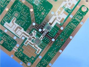
RO4360G2 Rogers 12mil ENEPIG 2-Layer DK6.15 High Frequency Custom PCB

Wangling F4BTMS220 2-Layer DK2.2 PCB 10 mil Core with Immersion Gold

Wangling F4BTME350 10mil DK3.5 High Frequency Substrate PCB 2-Layer Immersion Gold

Wangling F4BTM300 Custom 2-layer PCB 20mil DK3.0 Substrate with Immersion Gold
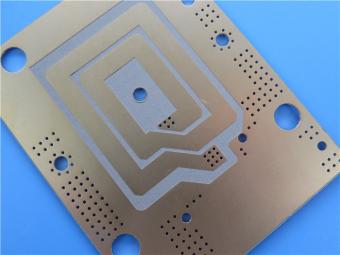
RF-35TC is a type of high frequency material from Taconic company. It offers a "best in class" low dissipation factor with high thermal conductivity.
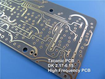
TLX offers reliability in a wide range of RF applications. This material is versatile due to its 2.45 - 2.65 DK range and available thicknesses and copper cladding. It is suitable for low layer count microwave designs.
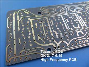
TLF-35A is another type of low cost RF material. It's the best choice for low cost, high volume commercial microwave and radio frequency applications.
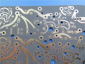
CER-10 is an organic-ceramic DK-10 laminate in the ORCER family of Taconic products. It is based on a woven glass reinforcement. CER-10 exhibits exceptional interlaminar bond strength and solder resistance.
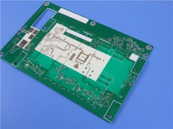
RO4360G2 laminates of Rogers Corporation are 6.15 Dk, low loss, glass-reinforced, hydrocarbon ceramic-filled thermoset materials that provide the ideal balance of performance and processing ease.
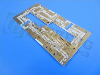
RF-60A is an organic-ceramic laminate in the ORganic CERamic(ORCER) family of Taconic products.
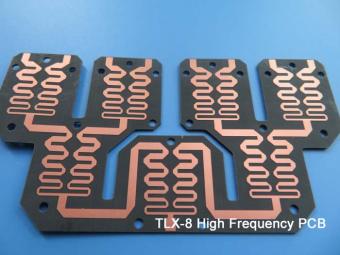
TLX is PTFE based fiberglass laminate, it is ideal for use in radar systems, mobile communications, microwave test equipment, microwave transmission devices and RF components.
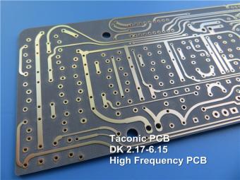
TLX offers reliability in a wide range of RF applications. This material is versatile due to its 2.45 - 2.65 DK range and available thicknesses and copper cladding. It is suitable for low layer count microwave designs
 6-11C Shidai Jingyuan, Fuyong, Baoan, Shenzhen, Guangdong, China 518103


For inquiries about our products or pricelist, please leave to us and we will be in touch within 24 hours.
© Copyright: 2026 Shenzhen Bicheng Electronics Technology Co., Ltd.. All Rights Reserved.

IPv6 network supported


