

 Call Us Now !
Tel : +86 755 27374946
Call Us Now !
Tel : +86 755 27374946
 Order Online Now !
Email : info@bichengpcb.com
Order Online Now !
Email : info@bichengpcb.com
Rogers AD255C PCB has a dielectric constant of 2.55 and 2.60, enabling excellent signal transmission at high frequencies.
Item NO.:
BIC-230-v253.0Order(MOQ):
1-10Payment:
T/TProduct Origin:
ChinaShipping Port:
ShenzhenLead Time:
7-10 days
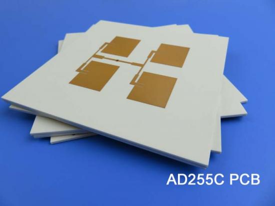
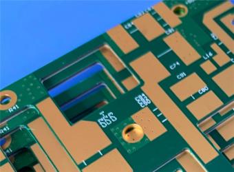
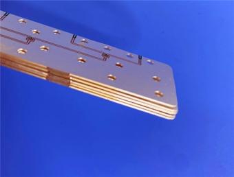
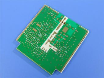
AD255C 60mil Rogers Material High Frequency PCB with Immersion Gold
Introduction
AD255C PCB is Rogers AD255C antenna grade laminate and the printed circuit boards (PCBs) that utilize this antenna material.
AD255C copper clad laminates combine a fluoropolymer resin system with selected ceramic materials and fiberglass reinforcement. This unique combination offers lower loss, lower thermal expansion, and lower passive intermodulation (PIM), making it suitable for a wide range of microwave and radio frequency applications in telecommunications infrastructure.
Micro-dispersed ceramics are incorporated into AD255C to improve its thermal stability by reducing its coefficient of thermal expansion (CTE) and enhancing phase stability at different temperatures.
Now, let's examine the data sheet to learn more about the properties of AD255C.
AD255C Typical Properties
One of the most remarkable features of AD255C Rogers Printed Circuit Board is its PIM rating of -159/-163 dBc. This rating is achieved using reverse treated ED copper foil, with typical values of -159 dBc at a thickness of 30mil and -163 dBc at a thickness of 60mil. These values were obtained through extensive PIM testing at Rogers, using a swept tone, reflected method on a 50Ω microstrip test vehicle at 1900 MHz.
Rogers AD255C PCB has a dielectric constant of 2.55 (process) and 2.60 (design), enabling excellent signal transmission at high frequencies.
More typical properties as follow:
|
Properties |
AD255C |
Units |
Test Conditions |
Test Method |
|
|
Electrical Properties |
|||||
|
PIM (30mil/60mil) |
-159/-163 |
dBc |
Reflected 43 dBm swept tones at 1900 MHz, S1/S1 |
Rogers Internal 50 ohm |
|
|
Dielectric Constant (process) |
2.55 |
- |
23°C @ 50% RH |
10 GHz |
IPC TM-650 2.5.5.5 |
|
Dielectric Constant (design) |
2.60 |
- |
C-24/23/50 |
10 GHz |
Microstrip Differential Phase Length |
|
Dissipation Factor (process) |
0.0013 |
- |
23°C @ 50% RH |
10 GHz |
IPC TM-650 2.5.5.5 |
|
Electrical Strength (dielectric strength) |
911 |
V/mil |
- |
- |
IPC TM-650 2.5.6.2 |
|
Thermal Coefficient of Dielectric Constant |
-110 |
ppm/ºC |
0°C to 100°C |
10 GHz |
IPC TM-650 2.5.5.5 |
|
Volume Resistivity |
7.4 x 10⁸ |
Mohm-cm |
C-96/35/90 |
- |
IPC TM-650 2.5.17.1 |
|
Surface Resistivity |
3.6 x 10⁷ |
Mohm |
C-96/35/90 |
- |
IPC TM-650 2.5.17.1 |
|
Dielectric Breakdown |
>40 |
kV |
D-48/50 |
X/Y direction |
IPC TM-650 2.5.6 |
|
Thermal Properties |
|||||
|
Decomposition Temperature (Td) |
>500 |
˚C |
2hrs @ 105˚C |
5% Weight Loss |
IPC TM-650 2.3.40 |
|
Thermal Conductivity |
0.35 |
W/mK |
- |
z direction |
ASTM D5470 |
|
Coefficient of Thermal Expansion - x |
34 |
ppm/˚C |
- |
-55˚C to 288˚C |
IPC TM-650 2.4.41 |
|
Coefficient of Thermal Expansion - y |
26 |
ppm/˚C |
- |
-55˚C to 288˚C |
IPC TM-650 2.4.41 |
|
Coefficient of Thermal Expansion - z |
196 |
ppm/˚C |
- |
-55˚C to 288˚C |
IPC TM-650 2.4.41 |
|
Time to Delamination |
>60 |
minutes |
as-received |
288˚C |
IPC TM-650 2.4.24.1 |
|
Mechanical Properties |
|||||
|
Copper Peel Strength after Thermal Stress |
2.4 |
N/mm (lbs/in) |
10s @288˚C |
35 μm foil |
IPC TM-650 2.4.8 |
|
Flexural Strength (MD/CMD) |
8.8/6.4 (60.7/44.1) |
MPa (ksi ) |
25°C ± 3°C |
- |
ASTM D790 |
|
Tensile Strength (MD/CMD) |
8.1/6.6 (55.8/45.5) |
MPa (ksi ) |
23°C/50% RH |
- |
ASTM D3039/D3039-14 |
|
Flex Modulus (MD/CMD) |
930/818 (6,412/5,640) |
MPa (ksi ) |
25°C ± 3°C |
- |
IPC-TM-650 Test Method 2.4.4 |
|
Dimensional Stability (MD/CMD) |
0.03/0.07 |
mils/inch |
after etch + bake |
- |
IPC-TM-650 2.4.39a |
|
Physical Properties |
|||||
|
Flammability |
V-0 |
- |
- |
- |
UL-94 |
|
Moisture Absorption |
0.03 |
% |
E1/105 +D48/50 |
- |
IPC TM-650 2.6.2.1 |
|
Density |
2.28 |
g/cm3 |
C-24/23/50 |
- |
ASTM D792 |
|
Specific Heat Capacity |
0.813 |
J/g°K |
2 hours at 105°C |
- |
ASTM E2716 |
AD255CPCB Capability
|
PCB material: |
Glass-reinforced, PTFE based Composites |
|
Designation: |
AD255C |
|
Dielectric constant: |
2.55 (10 GHz) |
|
Dissipation Factor |
0.0013 (10 GHz) |
|
Layer count: |
Double Sided PCB, Multi-layer PCB, Hybrid PCB |
|
Copper weight: |
1oz (35µm), 2oz (70µm) |
|
Dielectric thickness: |
20mil (0.508mm), 30mil (0.762mm), 40mil (1.016mm), 60mil (1.524mm), 125mil (3.175mm) |
|
PCB size: |
≤400mm X 500mm |
|
Solder mask: |
Green, Black, Blue, Yellow, Red, Purple etc. |
|
Surface Finish: |
Immersion gold, Hot air soldering level (HASL), Immersion silver, Immersion tin, OSP, Pure gold plated, ENEPIG, Bare copper, etc.. |
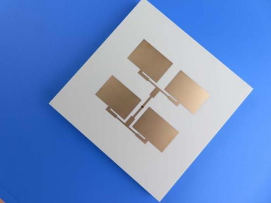
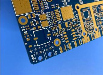
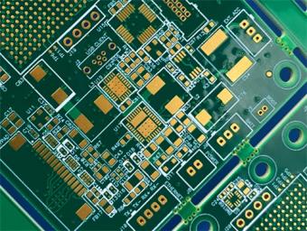
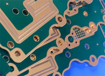
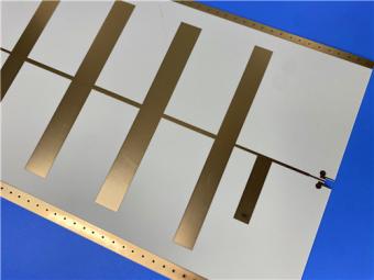
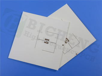
A Piece of AD255C PCB
There is a 60mil AD255C PCB with immersion gold coating, specifically designed for automotive telematics antenna systems.
These PCBs also excel in cellular infrastructure base station antennas, commercial satellite radio antennas, and more.

Conclusion
AD255C high frequency PCBs can be processed using standard equipment and chemical processes for plating, imaging, and etching circuit patterns. It is important to preserve the post-etch laminate surface, as the remaining topography promotes improved adhesion to solder masks.


Previous:
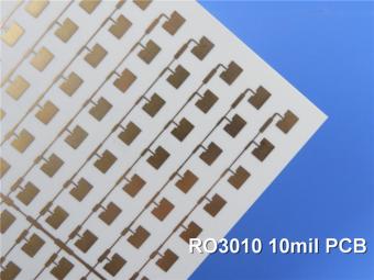
RO3206 50mil Rogers laminate High Frequency PCB with Immersion GoldNext:
RO3010 60mil Rogers 3010 Substrate High Frequency PCB with Immersion SilverIf you have questions or suggestions,please leave us a message,we will reply you as soon as we can!
Categories
New Products
20-Layer Panasonic TU872 HDI PCB ENEPIG 3.0mm Finished Thick Laser-drilled Blind Vias
10-Layer Rogers RO4003C + 370HR FR4 Hybrid Laminate PCB ENIG Impedance Control
8-Layer 10oz Heavy Copper TU-865 Substrate PCB With ENIG Blind &Buried Via
4-Layer Rogers RO3210 + RO4450F PCB ISIG Surface Finish 1.321mm With Blind Via
4-Layer Rogers RO3003+TG170 FR-4 Hybrid PCB Immersion Silver Green Solder Mask
WL-CT440 PCB 30mil 0.762mm Wangling Laminate ENIG Finish No Solder Mask
TP1600 PCB 31.49mil High DK16 Wangling Laminate Pure Gold Plating
TLX-9 PCB 10mil 0.254mm Taconic High Frequency Laminate EPIG Nickle-free

RF-10 25mil Taconic PCB Materials stands out as a high-performance solution for RF applications. Its exceptional electrical properties, dimensional stability, thermal conductivity, and adhesion characteristics make it an ideal choice for demanding applications.
The PCB has a 4-layer hybrid stackup with a 0.5oz+plating ground layer, two 1oz ground layers, and a 0.5oz+plating signal layer.
The dimensions of the board are 55.00 x 26.00 mm, with a tolerance of +/- 0.15mm. The board has 16 components, 26 total pads, 9 through-hole pads, 10 top SMT pads, 7 bottom SMT pads, 77 vias, and 82 nets.
Rogers RO4003C PCB is an innovative and advanced circuit board that is made with high-quality materials.
The RO4350B PCB offers a range of benefits that make it an ideal choice for high-frequency applications. Its low dielectric loss and high thermal conductivity make it perfect for high-frequency applications such as RF and microwave circuits.
Bicheng PCB Ships High-Quality PCBs with Shengyi Tg150 ℃ S1000H Material and Advanced Stackup
Rogers RO3010 PCB is ideal for a wide range of high-frequency applications, including power amplifiers, filters, couplers, and antennas.
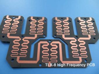
TLX-8 features low dielectric loss, low moisture absorption, and excellent thermal stability, making it ideal for high-frequency and high-speed applications. It has a low dissipation factor, which helps to minimize signal loss and distortion.
 6-11C Shidai Jingyuan, Fuyong, Baoan, Shenzhen, Guangdong, China 518103


For inquiries about our products or pricelist, please leave to us and we will be in touch within 24 hours.
© Copyright: 2026 Shenzhen Bicheng Electronics Technology Co., Ltd.. All Rights Reserved.

IPv6 network supported


