

 Call Us Now !
Tel : +86 755 27374946
Call Us Now !
Tel : +86 755 27374946
 Order Online Now !
Email : info@bichengpcb.com
Order Online Now !
Email : info@bichengpcb.com
The F4BTME series laminates are manufactured through a meticulous process that involves the scientific formulation of glass fiber cloth, nano-ceramic fillers, and polytetrafluoroethylene (PTFE) resin.
Item NO.:
BIC-088-v363.0Order(MOQ):
1-10Payment:
T/TProduct Origin:
ChinaShipping Port:
ShenzhenLead Time:
7-10 days
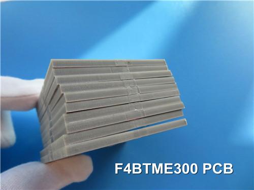
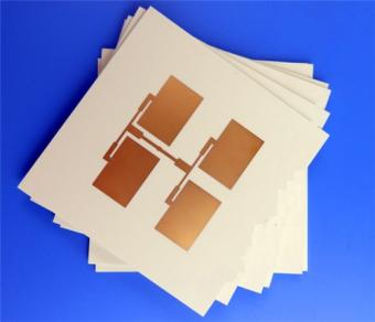
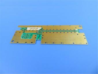
F4BTME300 High Frequency PCB PTFE RF PCB Built on 3.0mm thick with Immersion Silver
(PCB's are custom-made products, the picture and parameters shown are just for reference)
Hello everybody,
Today we talk abouta type of F4BTME high frequency circuit board - F4BTME300 PCB.
This F4BTME300 PCB features a size of 170 mm x 95 mm and is designed as a double-sided board with two layers. It supports surface mount components, while through-hole components are not included in this design. The layer stackup consists of a top layer with 35 µm (1 oz) copperstarting with 0.5oz plating, paired with a core material of F4BTME300 that is 3.0 mm thick. The bottom layer also comprises 35 µm (1 oz) copper with plating.This F4BTME PCB uses immersion silver, providing excellent solderability and protection. Notably, there is no solder mask applied to this board, allowing for direct access to the copper layers.
PCB Specifications
| PCB SIZE | 170 x 95mm=1PCS |
| BOARD TYPE | Double sided PCB |
| Number of Layers | 2 layers |
| Surface Mount Components | YES |
| Through Hole Components | NO |
| LAYER STACKUP | copper ------- 35um(0.5 oz+plate )TOP layer |
| F4BTME300 -3.0mm | |
| copper ------- 35um(0.5 oz + plate) BOT Layer | |
| TECHNOLOGY | |
| Minimum Trace and Space: | 7 mil / 7 mil |
| Minimum / Maximum Holes: | 0.5 mm / 0.6 mm |
| Number of Different Holes: | 5 |
| Number of Drill Holes: | 16 |
| Number of Milled Slots: | 0 |
| Number of Internal Cutouts: | 2 |
| Impedance Control: | no |
| Number of Gold finger: | 0 |
| BOARD MATERIAL | |
| Glass Epoxy: | F4BTME300 DK 3.0 |
| Final foil external: | 1oz |
| Final foil internal: | N/A |
| Final height of PCB: | 3.1 mm ±10% |
| PLATING AND COATING | |
| Surface Finish | Immersion silver |
| Solder Mask Apply To: | no |
| Solder Mask Color: | no |
| Solder Mask Type: | no |
| CONTOUR/CUTTING | Routing |
| MARKING | |
| Side of Component Legend | NO |
| Colour of Component Legend | NO |
| Manufacturer Name or Logo: | Marked on the board in a conductor and leged FREE AREA |
| VIA | Non-Plated through hole(PTH), minimum size 0.5mm. |
| FLAMIBILITY RATING | UL 94-V0 Approval MIN. |
| DIMENSION TOLERANCE | |
| Outline dimension: | 0.0059" |
| Board plating: | 0.0029" |
| Drill tolerance: | 0.002" |
| TEST | 100% Electrical Test prior shipment |
| TYPE OF ARTWORK TO BE SUPPLIED | email file, Gerber RS-274-X, PCBDOC etc |
| SERVICE AREA | Worldwide, Globally. |

The basic color of F4BTME300 PCB is brown.
F4BTME High Frequency Laminates
The F4BTME series laminates are manufactured through a meticulous process that involves the scientific formulation of glass fiber cloth, nano-ceramic fillers, and polytetrafluoroethylene (PTFE) resin.
These F4BTME substrates are built upon the F4BM dielectric layer and incorporate high dielectric constant and low loss nano-ceramics. This integration results in enhanced dielectric constant, superior heat resistance, reduced thermal expansion coefficient, increased insulation resistance, and improved thermal conductivity, all while maintaining low loss characteristics.
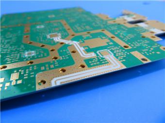
Furthermore, F4BTME laminates are specifically paired with reverse-treated RTF copper foil, providing exceptional performance in terms of PIM, precise line control, and minimized conductor loss.
The dielectric constant ranges from2.98 to 3.5 and EDCopperfoil available with 0.5oz, 1oz, 1.5oz and 2oz, RTF copper available with 0.5oz and 1oz; thicknessavailableof from 0.254mm to12.0mm.
Data Sheet (F4BTME300)
| Product Technical Parameters | Product Models & Data Sheet | ||||||
| Product Features | Test Conditions | Unit | F4BTME298 | F4BTME300 | F4BTME320 | F4BTME350 | |
| Dielectric Constant (Typical) | 10GHz | / | 2.98 | 3.0 | 3.2 | 3.5 | |
| Dielectric Constant Tolerance | / | / | ±0.06 | ±0.06 | ±0.06 | ±0.07 | |
| Loss Tangent (Typical) | 10GHz | / | 0.0018 | 0.0018 | 0.0020 | 0.0025 | |
| 20GHz | / | 0.0023 | 0.0023 | 0.0026 | 0.0035 | ||
| Dielectric Constant Temperature Coefficient | -55 º~150ºC | PPM/℃ | -78 | -75 | -75 | -60 | |
| Peel Strength | 1 OZ F4BTM | N/mm | >1.6 | >1.6 | >1.6 | >1.6 | |
| 1 OZ F4BTME | N/mm | >1.4 | >1.4 | >1.4 | >1.4 | ||
| Volume Resistivity | Standard Condition | MΩ.cm | ≥1×10^7 | ≥1×10^7 | ≥1×10^7 | ≥1×10^7 | |
| Surface Resistivity | Standard Condition | MΩ | ≥1×10^6 | ≥1×10^6 | ≥1×10^6 | ≥1×10^6 | |
| Electrical Strength (Z direction) | 5KW,500V/s | KV/mm | >26 | >30 | >32 | >32 | |
| Breakdown Voltage (XY direction) | 5KW,500V/s | KV | >34 | >35 | >40 | >40 | |
| Coefficientof Thermal Expansion | XY direction | -55 º~288ºC | ppm/ºC | 15,16 | 15,16 | 13,15 | 10,12 |
| Z direction | -55 º~288ºC | ppm/ºC | 78 | 72 | 58 | 51 | |
| Thermal Stress | 260℃, 10s,3 times | No delamination | No delamination | No delamination | No delamination | ||
| Water Absorption | 20±2℃, 24 hours | % | ≤0.05 | ≤0.05 | ≤0.05 | ≤0.05 | |
| Density | Room Temperature | g/cm3 | 2.25 | 2.25 | 2.20 | 2.20 | |
| Long-Term Operating Temperature | High-Low Temperature Chamber | ℃ | -55~+260 | -55~+260 | -55~+260 | -55~+260 | |
| Thermal Conductivity | Z direction | W/(M.K) | 0.42 | 0.42 | 0.50 | 0.54 | |
| PIM | Only applicable to F4BTME | dBc | ≤-160 | ≤-160 | ≤-160 | ≤-160 | |
| Flammability | / | UL-94 | V-0 | V-0 | V-0 | V-0 | |
| Material Composition | / | / |
PTFE, Fiberglass Cloth, nano-ceramics F4BTM paired with ED copper foil, F4BTME paired with reverse-treated (RTF) copper foil. |
||||


Previous:
F4BM265 High Frequency PCB DK 2.65 PTFE RF Circuit Board with 3oz Copper Coating Immersion GoldNext:
F4BTM350 High Frequency PCB Board 1.5mm PTFE Plate with 3oz Copper and Immersion SilverIf you have questions or suggestions,please leave us a message,we will reply you as soon as we can!
Categories
New Products

2-Layer 20mil FSD1020T ENIG High-Frequency PCB with Via Resin Plugged and Capped

4-Layer F4BM265+S1000-2M Material Hyrbid PCB with Blind Via Impedance Control & ENIG

4-Layer Wangling WL-CT338 + FR4 Hybrid PCB ENIG Green Solder Mask White Silkscreen

6-layer Isola 370HR High-Tg FR-4 PCB 2μ" ENIG Impedance Controlled
6-Layer RO4003C + FR4 Mixed Dielectric PCB with Hard Gold Plating Blind Via
30mil Taconic CER-10 2-layer Immersion Silver DK10 High Frequency Laminate PCB
31mil Rogers RT/duroid 5880 Double-sided Bare Copper ENIG Finished PCB
Wangling TFA294 Laminate 40mil Immersion Silver No Solder Mask Silkscreen Custom PCB

RF-10 25mil Taconic PCB Materials stands out as a high-performance solution for RF applications. Its exceptional electrical properties, dimensional stability, thermal conductivity, and adhesion characteristics make it an ideal choice for demanding applications.
The PCB has a 4-layer hybrid stackup with a 0.5oz+plating ground layer, two 1oz ground layers, and a 0.5oz+plating signal layer.
The dimensions of the board are 55.00 x 26.00 mm, with a tolerance of +/- 0.15mm. The board has 16 components, 26 total pads, 9 through-hole pads, 10 top SMT pads, 7 bottom SMT pads, 77 vias, and 82 nets.
Rogers RO4003C PCB is an innovative and advanced circuit board that is made with high-quality materials.
The RO4350B PCB offers a range of benefits that make it an ideal choice for high-frequency applications. Its low dielectric loss and high thermal conductivity make it perfect for high-frequency applications such as RF and microwave circuits.
Bicheng PCB Ships High-Quality PCBs with Shengyi Tg150 ℃ S1000H Material and Advanced Stackup
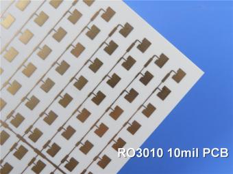
Rogers RO3010 PCB is ideal for a wide range of high-frequency applications, including power amplifiers, filters, couplers, and antennas.
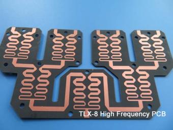
TLX-8 features low dielectric loss, low moisture absorption, and excellent thermal stability, making it ideal for high-frequency and high-speed applications. It has a low dissipation factor, which helps to minimize signal loss and distortion.
 6-11C Shidai Jingyuan, Fuyong, Baoan, Shenzhen, Guangdong, China 518103


For inquiries about our products or pricelist, please leave to us and we will be in touch within 24 hours.
© Copyright: 2026 Shenzhen Bicheng Electronics Technology Co., Ltd.. All Rights Reserved.

IPv6 network supported


