

 Call Us Now !
Tel : +86 755 27374946
Call Us Now !
Tel : +86 755 27374946
 Order Online Now !
Email : info@bichengpcb.com
Order Online Now !
Email : info@bichengpcb.com
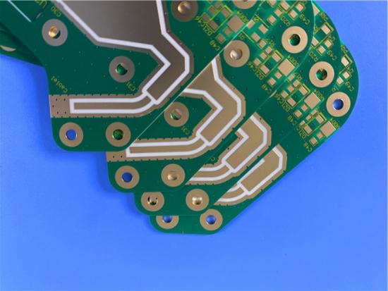
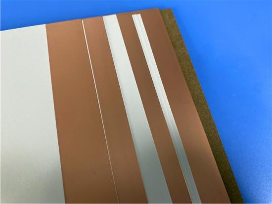
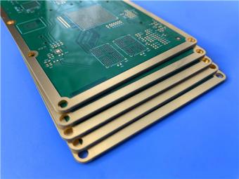
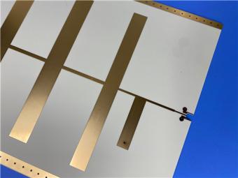
This 20mil AD250C pure gold PCB with pure gold finish is a purpose-built high-frequency antenna solution.
Item NO.:
BIC-625-v710Order(MOQ):
1-10Payment:
T/TProduct Origin:
ChinaShipping Port:
ShenzhenLead Time:
7-10 days
Rogers 20mil AD250C PCB Pure Gold High-Frequency Antenna Circuit Board
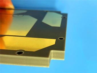
This article specifies a 2-layer rigid PCB on Rogers AD250C high-frequency laminate with pure gold finish. At 0.6 mm finished thickness with a 20 mil dielectric core, it targets antenna applications requiring low loss, controlled impedance, and excellent PIM performance.
Part I covers PCB construction, stackup, and statistics; Part II reviews the AD250C copper-clad laminate, including its full datasheet, standard offerings, and material science.
The 20mil AD250C PCB is a 2-layer rigid board measuring 55.36 by 76.2 mm, tolerance plus or minus 0.15 mm. Built on glass-reinforced PTFE, it carries 1 oz copper on both layers and a pure gold finish for superior conductivity and corrosion resistance. Minimum trace and space is 4/6 mils, minimum drill 0.4 mm. Every board passes 100 percent electrical test and meets IPC-Class-2, with worldwide availability.
The table below summarizes the complete construction specifications.
|
Parameter |
Specification |
|
Base Material |
AD250C |
|
Layer Count |
2-layer rigid |
|
Dimensions |
55.36 x 76.2 mm (+/-0.15) |
|
Min Trace/Space |
4/6 mils |
|
Min Hole Size |
0.4 mm |
|
Via Type |
Through-hole only |
|
Finished Thickness |
0.6 mm |
|
Cu Weight |
1 oz outer layers |
|
Via Plating |
20 micron |
|
Surface Finish |
Pure Gold |
|
Top Silkscreen |
Yellow |
|
Bottom Silkscreen |
None |
|
Top Solder Mask |
Green |
|
Bottom Solder Mask |
Green |
|
Electrical Test |
100% prior to ship |
|
Quality Standard |
IPC-Class-2 |
|
Artwork |
Gerber RS-274-X |
|
Availability |
Worldwide |
A symmetric 2-layer stackup is centered on a 20 mil AD250C core.
|
Layer |
Material |
Thickness |
|
Copper L1 |
Copper (1 oz) |
35 micron |
|
Core |
AD250C |
0.508 mm (20 mil) |
|
Copper L2 |
Copper (1 oz) |
35 micron |
The design comprises 36 components, 51 pads, and 49 through-hole vias across 2 nets.
|
Metric |
Count |
|
Components |
36 |
|
Total Pads |
51 |
|
Thru-Hole Pads |
24 |
|
Top SMT Pads |
27 |
|
Bottom SMT Pads |
0 |
|
Vias |
49 |
|
Nets |
2 |
Pure gold finish provides a flat, highly conductive RF contact surface, avoiding the nickel layer in ENIG that adds loss at microwave frequencies.
AD250C yields a controlled Dk of 2.5 plus or minus 0.04 at 10 GHz and Df of 0.0013, ensuring consistent impedance and minimal insertion loss. PIM of -159 dBc at 1900 MHz suppresses intermodulation distortion critical for base station arrays. The 4/6 mil trace capability enables compact feed networks; 20 micron via plating secures reliable interconnects. No blind or buried vias simplifies fabrication and improves yield.
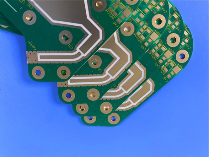
Cellular base station antennas,
Automotive telematics antenna systems
Commercial satellite radio antennas.
Low loss and strong PIM performance benefit multi-element arrays where signal purity governs network capacity.
This 20mil AD250C pure gold PCB with pure gold finish is a purpose-built high-frequency antenna solution.
A low-loss PTFE composite substrate, 4/6 mil trace geometry, 100 percent electrical testing, and IPC-Class-2 construction combine to deliver repeatable RF performance. The symmetric stackup on a 20 mil core offers excellent dimensional stability for demanding wireless designs.
Part II: AD250C CCL Material Knowledge
Rogers AD Series antenna materials are high-performance specialty laminates engineered for wireless antenna markets. These glass-reinforced, PTFE-based composites deliver controlled dielectric constant, low loss, and very good PIM. Woven glass reinforcement affords processability and high-yield fabrication. All AD Series products offer standard ED or reverse-treated ED copper foil to reduce circuit loss and antenna PIM.
AD250C is a PTFE composite reinforced with woven glass fiber. The PTFE matrix gives inherently low dielectric loss and chemical stability; glass fabric improves dimensional stability and handling. Unlike ceramic-filled PTFE, glass reinforcement offers superior drillability and lower tool wear. Reverse-treated foil reduces conductor loss and PIM by minimizing roughness at the copper-dielectric interface. The material shows 0.04 percent moisture absorption, 2.6 N per mm peel strength, and decomposition above 500 degrees Celsius.
The full datasheet covers electrical, thermal, mechanical, and physical properties.
|
Property |
Value |
Units |
Conditions |
Method |
|
Electrical |
||||
|
Dk (process) |
2.52 |
- |
23C, 10 GHz |
IPC 2.5.5.5 |
|
Dk (design) |
2.50 |
- |
10 GHz |
Microstrip |
|
Df |
0.0013 |
- |
23C, 10 GHz |
IPC 2.5.5.5 |
|
Thermal Coeff Dk |
-117 |
ppm/C |
0-100C |
IPC 2.5.5.5 |
|
Volume Resistivity |
4.8e8 |
MOhm-cm |
C96/35/90 |
IPC 2.5.17.1 |
|
Surface Resistivity |
4.1e7 |
MOhm |
C96/35/90 |
IPC 2.5.17.1 |
|
Elec. Strength |
979 |
V/mil |
- |
IPC 2.5.6.2 |
|
Dielectric Breakdown |
>40 |
kV |
X/Y dir |
IPC 2.5.6 |
|
PIM |
-159/-163 |
dBc |
1900 MHz |
Rogers |
|
Thermal |
||||
|
Td |
>500 |
C |
5% loss |
IPC 2.3.40 |
|
CTE X |
47 |
ppm/C |
-55-288C |
IPC 2.4.41 |
|
CTE Y |
29 |
ppm/C |
-55-288C |
IPC 2.4.41 |
|
CTE Z |
196 |
ppm/C |
-55-288C |
IPC 2.4.41 |
|
Thermal Cond. |
0.33 |
W/m.K |
Z dir |
ASTM D5470 |
|
T288 Delam. |
>60 |
min |
288C |
IPC 2.4.24.1 |
|
Mechanical |
||||
|
Peel Strength |
2.6 |
N/mm |
288C |
IPC 2.4.8 |
|
Flexural Strength |
60.7/44.1 |
MPa |
25C |
ASTM D790 |
|
Tensile Strength |
41.4/38.6 |
MPa |
23C |
ASTM D3039 |
|
Flex Modulus |
6102/5364 |
MPa |
25C |
IPC 2.4.4 |
|
Dim. Stability |
0.02/0.06 |
mils/in |
etch+bake |
IPC 2.4.39a |
|
Physical |
||||
|
Flammability |
V-0 |
- |
- |
UL 94 |
|
Moisture Abs. |
0.04 |
% |
E1/105 |
IPC 2.6.2.1 |
|
Density |
2.28 |
g/cm3 |
C24/23/50 |
ASTM D792 |
|
Spec. Heat |
0.813 |
J/g.K |
105C |
ASTM E2716 |
Three standard thicknesses are available with matching panel sizes and copper options.
|
Thickness |
Panel Sizes |
Copper Cladding |
|
0.020" (0.508 mm) |
18x12, 18x24 in |
ED/RT ED: 1/2oz, 1oz |
|
0.030" (0.762 mm) |
12x18, 24x18 in |
ED/RT ED: 1/2oz, 1oz |
|
0.060" (1.524 mm) |
12x18, 24x18 in |
ED/RT ED: 1/2oz, 1oz |
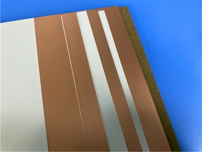
Figure 1: AD250C copper-clad laminate with copper foil and dielectric layers.
AD250C substrate features process Dk of 2.52 and design Dk of 2.50, among the lowest in the AD Series, ideal for wideband elements where low Dk minimizes phase velocity variation. Df of 0.0013 at 10 GHz is roughly an order of magnitude below FR-4, reducing insertion loss. Decomposition above 500 degrees and T288 delamination beyond 60 minutes ensure reflow robustness. CTE of 47, 29, and 196 ppm per degree in X, Y, and Z reflects glass-controlled in-plane stability far better than unreinforced PTFE. Thermal conductivity of 0.33 W per m-K provides modest heat spreading. Peel strength of 2.6 N per mm confirms strong adhesion. UL 94 V-0 and 0.04 percent moisture absorption suit humid outdoor base stations.
Rogers AD250C is a purpose-engineered glass-reinforced PTFE laminate combining controlled low Dk, ultra-low Df, and excellent PIM in a high-yield processable format. Its full property set across electrical, thermal, mechanical, and physical domains makes it dependable for cellular, automotive, and satellite antennas. Multiple thicknesses, panel sizes, and foil options offer design flexibility, while V-0 flammability and low moisture absorption ensure long-term field reliability.





If you have questions or suggestions,please leave us a message,we will reply you as soon as we can!
Categories
New Products

Rogers 20mil RT/duroid 6202 2-layer ENIG High-Frequency Microwave PCB

Rogers 20mil AD250C PCB Pure Gold High-Frequency Antenna Circuit Board

8-Layer Hybrid RF PCB: RO4350B + TG170 FR-4 + RO4003C with RO4450F Bondply

4-Layer Rogers RO3010 Hybrid PCB Immersion Silver 2.8mm Finished Thickness

4-Layer 20mil Rogers RO3210 ISIG High-Frequency PCB with Controlled Depth Milling
4-Layer 10mil RO3003 + Tg170 FR-4 Hybrid PCB with ENIG and Controlled Depth Milling
2-Layer F4BM233 4.0mm Wangling Substrate High-Frequency Custom PCB with ENIG Finish
Wangling WL-CT615 8mil Ultra-Thin High-Frequency 2-Layer PCB ENEPIG Finish
Polytetrafluoroethylene (Short for PTFE), commonly known as "plastic king ", is a polymer compound made of tetrafluoroethylene by polymerization. It has excellent chemical stability, corrosion resistance, sealing, high lubrication and non-viscosity, electrical insulation and good aging resistance.
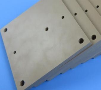
Rogers TMM4 thermoset microwave material is ceramic, hydrocarbon, thermoset polymer composite designed for high plated-through-hole reliability stripline and microstrip applications.
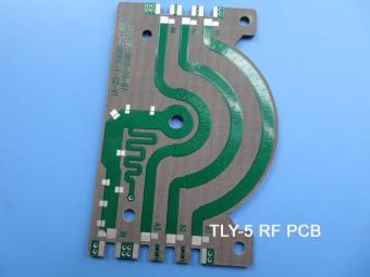
Taconic TLY laminates are a type of low loss laminates. They are manufactured with very light weight woven fiberglass and are more dimensionally stable than chopped fiber reinforced PTFE composites.
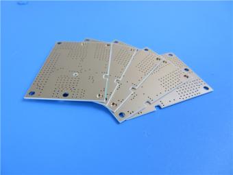
RO3203 laminates combine the surface smoothness of a non-woven PTFE laminate, for finer line etching tolerances, with the rigidity of a woven-glass PTFE laminate. These materials can be fabricated into printed circuit boards using
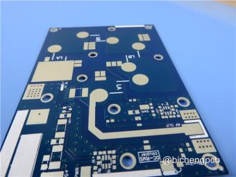
This type of immersion silver RF PCB is made on one of Taconic’s ORCER family material: RF-45.
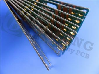
Rogers’ TMM10 thermoset microwave materials are ceramic, hydrocarbon, thermoset polymer composites designed for high plated-thru-hole reliability stripline and microstrip applications.
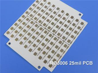
Rogers RO3006 was designed to offer exceptional electrical and mechanical stability at competitive prices.
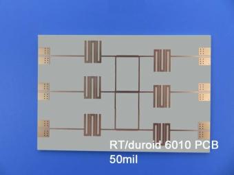
RT/duroid 6010LM microwave laminates feature ease of fabrication and stability in use. This property results in the possibility of mass production and reducing the cost of goods.
 6-11C Shidai Jingyuan, Fuyong, Baoan, Shenzhen, Guangdong, China 518103


For inquiries about our products or pricelist, please leave to us and we will be in touch within 24 hours.
© Copyright: 2026 Shenzhen Bicheng Electronics Technology Co., Ltd.. All Rights Reserved.

IPv6 network supported


