Rogers
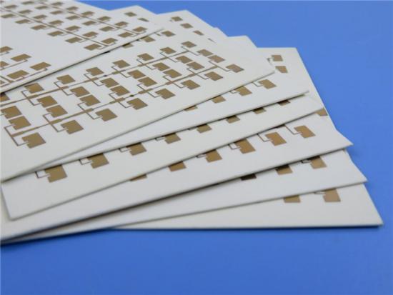
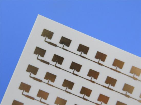
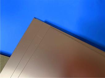
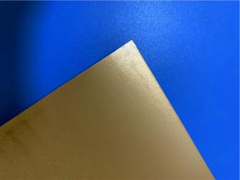
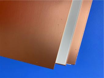
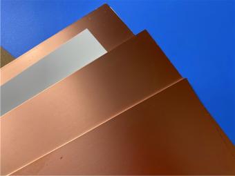
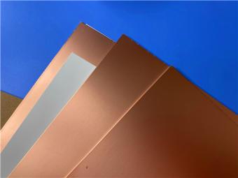
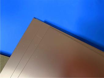
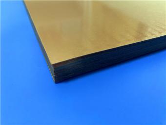
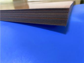
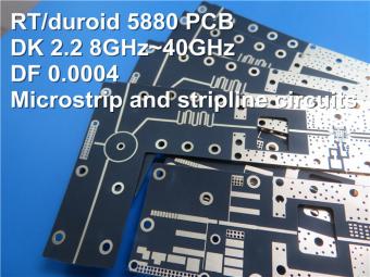
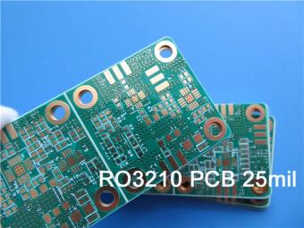
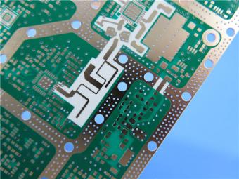
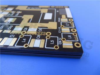
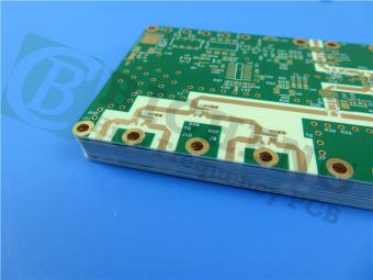
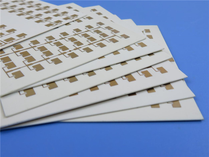
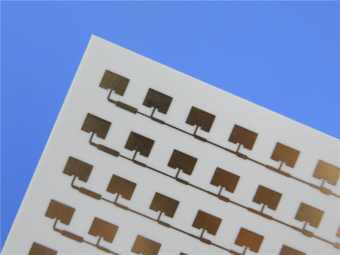
RT/duroid 6035 High Frequency PCB Built on 10mil Core With Immersion Gold for
Filters
(Printed
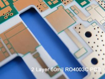
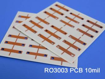
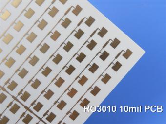
Circuit Boards are custom-made products, the picture and parameters shown are
just for reference)
The
RT/ duroid 6035HTC material consists
of a ceramic-filled PTFE composite dielectric and a standard or reverse-treated
electrolytic (ED) copper foil. Because of its high thermal conductivity, the
material is widely used in microwave amplifiers with hundreds of watts of power
for efficient thermal management. It has a relative dielectric constant of 3.50
at 10GH on the Z-axis, and its tolerance across the board remains within +005,
thus keeping the impedance of the energy transfer line consistent. The CTE of
the x and y axes is 19ppm/C, which is close to matching the CTE of copper.
Duroid
6035HTC laminates are ceramic filled teflon components for high frequency
circuits with high thermal conductivity and are designed for high power RF and microwave applications. Duroid 6000 laminates also offer superior electronic
performance for a wide range of high reliability, aerospace applications.
Of
course, correct thermal management in circuit design is not simply a matter of
choosing the circuit laminate with the best thermal dependency. There are many
other factors that affect the temperature of a circuit operating at a given
power level and frequency. For example, the circuit material is characterized
by the excitation factor, which is the loss caused by the dielectric material.
There are also losses through a conductive transfer line (such as making a
strip or ribbon circuit), and the higher the insertion loss, the more heat the
transmission line generates at a higher power level. The roughness of the hinge
conductor on a PCB can lead to increased insertion loss, especially at higher
frequencies.
In
addition, the choice of the dielectric constant of the PCB material will
determine the size and density of the microwave/DRAMA circuit board, since the
size of the microwave transmission line structure depends on the wavelength of
the signal to be processed. When the relative permittivity is large, the size
of the transmission line required to achieve a given impedance will be smaller,
and the power handling capability of the PCB will be limited by the width and
loss of the wire and the ground plane spacing. For example, for an amplifier
circuit, choosing a PCB material with a small relative dielectric constant can
make the line wider for a given impedance, thus improving the heat flow. The
use of PCB materials with larger relative permittivity will lead to smaller
size of transfer lines and more closely spaced circuits, so hot spots may be
formed in high-power circuits. In addition, the selection of materials with low
dissipation factor helps to minimize the insertion loss of the transmission line
and optimize the gain of the amplifier circuit.
Features/Benefits:
1.High Thermal conductivity
Improved
dielectric heat dissipation enables lower operating temperatures for high power
applications
2.Low loss tangent
Excellent
high frequency performance
3.Thermally stable low profile and reverse
treat copper foil
Lower
insertion loss and excellent thermal stability of traces
4.Advanced filler system
Improved
drill ability and extended tool life compared to alumina containing circuit
materials
Some
Typical Applications:
1.High Power RF and Microwave Amplifiers
2.Power amplifiers, Couplers, Filters
3.Combiners, Power Dividers
PCB
Capability(RT/duroid 6035HTC):
|
PCB Capability (RT/duroid 6035HTC)
|
|
PCB Material:
|
Ceramic-filled PTFE composites
|
|
Designation:
|
RT/duroid 6035HTC
|
|
Dielectric constant:
|
3.50±0.05
|
|
Layer count:
|
Double Layer, Multilayer, Hybrid PCB
|
|
Copper
weight:
|
0.5oz (17 µm), 1oz (35µm), 2oz (70µm)
|
|
PCB thickness:
|
10mil
(0.254mm), 20mil(0.508mm), 30mil (0.762mm), 60mil(1.524mm)
|
|
PCB size:
|
≤400mm X 500mm
|
|
Solder mask:
|
Green, Black, Blue,
Yellow, Red etc.
|
|
Surface
finish:
|
Bare copper, HASL,
ENIG, OSP etc..
|
Data Sheet of RT/duroid 6035HTC:
|
RT/duroid
6035HTC Typical Value
|
|
Property
|
RT/duorid 6035HTC
|
Direction
|
Units
|
Condition
|
Test Method
|
|
Dielectric Constant,εProcess
|
3.50±0.05
|
Z
|
|
10 GHz/23℃
|
IPC-TM-650
2.5.5.5 Clamped Stripline
|
|
Dielectric Constant,εDesign
|
3.6
|
Z
|
|
8 GHz - 40
GHz
|
Differential Phase Length Method
|
|
Dissipation
Factor
|
0.0013
|
Z
|
|
10 GHz/23℃
|
IPC-TM-650 2.5.5.5
|
|
Thermal Coefficient of ε
|
-66
|
Z
|
ppm/℃
|
-50℃to 150℃
|
mod IPC-TM-650, 2.5.5.5
|
|
Volume Resistivity
|
108
|
|
MΩ.cm
|
A
|
IPC-TM-650, 2.5.17.1
|
|
Surface Resistivity
|
108
|
|
MΩ
|
A
|
IPC-TM-650, 2.5.17.1
|
|
Dimensional Stability
|
-0.11 -0.08
|
CMD MD
|
mm/m
(mils/inch)
|
0.030"
1oz EDC foil Thickness after etch '+E4/105
|
IPC-TM-650 2.4.39A
|
|
Tensile Modulus
|
329 244
|
MD CMD
|
kpsi
|
40 hrs @23℃/50RH
|
ASTM D638
|
|
Moisure Absorption
|
0.06
|
|
%
|
D24/23
|
IPC-TM-650 2.6.2.1 ASTM D570
|
Coefficient of Thermal Expansion (-50℃to 288℃)
|
19 19 39
|
X Y Z
|
ppm/℃
|
23℃/ 50% RH
|
IPC-TM-650 2.4.41
|
|
Thermal Conductivity
|
1.44
|
|
W/m/k
|
80℃
|
ASTM C518
|
|
Density
|
2.2
|
|
gm/cm3
|
23℃
|
ASTM D792
|
|
Copper Peel Stength
|
7.9
|
|
pli
|
20 sec. @288℃
|
IPC-TM-650 2.4.8
|
|
Flammability
|
V-0
|
|
|
|
UL 94
|
|
Lead-Free Process Compatible
|
Yes
|
|
|
|
|
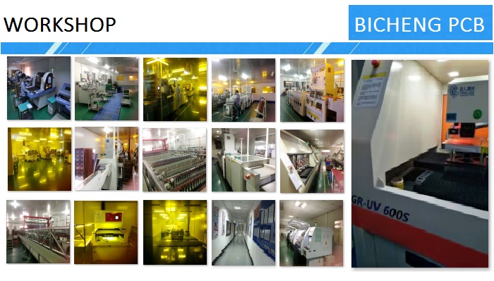
BICHENG PCB WORKSHOP:
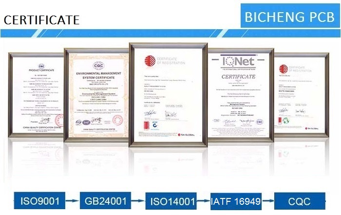
BICHENG PCB CERTIFICATE:
BICHENG MAIN COURIERS:


 Call Us Now !
Tel : +86 755 27374946
 Order Online Now !
Email : info@bichengpcb.com

