

 Call Us Now !
Tel : +86 755 27374946
Call Us Now !
Tel : +86 755 27374946
 Order Online Now !
Email : info@bichengpcb.com
Order Online Now !
Email : info@bichengpcb.com
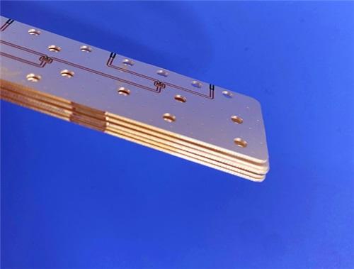
RO3003’s low loss, high stability, and wide frequency bandwidth make it the optimal choice for the core high-frequency layer of the 4-layer hybrid PCB.
Item NO.:
BIC-567-v652.0Order(MOQ):
1-10Payment:
T/TProduct Origin:
ChinaShipping Port:
ShenzhenLead Time:
7-10 days
4-Layer Rogers RO3003+TG170FR-4 Hybrid PCB Immersion Silver Green Solder Mask
Overview
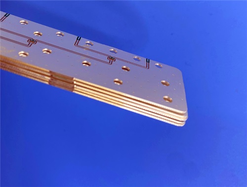
This 4-layer hybrid printed circuit board (PCB) integrates Rogers RO3003 high-frequency ceramic-filled PTFE laminate and high-temperature TG170 FR-4 material, engineered to deliver superior radio frequency (RF) performance, mechanical stability, and cost-efficiency for commercial microwave, automotive radar, satellite communication, and wireless broadband applications.
With a precision-engineered layer stacking, this hybrid circuit board PCB resolves the core pain points of pure high-frequency material cost constraints and pure FR-4 insufficient RF performance in high-frequency signal transmission. It adopts immersion silver surface finishing, green solder mask on the top layer, and no solder mask on the bottom layer to balance signal integrity, heat dissipation, and assembly adaptability. All boards undergo 100% electrical testing before shipment to guarantee long-term reliability in extreme thermal and operational environments.
PCB Construction Details
This section summarizes the core structural parameters of the 4-layer hybrid PCB, covering base materials, dimensions, layer thickness, copper weight, surface treatment, and solder mask configuration, all strictly controlled to meet high-frequency application requirements.
|
Parameter |
Specification |
|
Base Material |
Rogers RO3003 + TG170 FR-4 |
|
Layer Count |
4 layers |
|
Board Dimensions |
52mm × 77mm (per piece), tolerance ±0.15mm |
|
Via Type |
No blind vias, no buried vias (only through-hole vias) |
|
Finished Board Thickness |
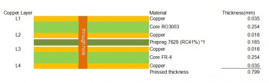
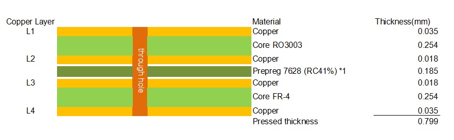
0.8mm |
|
Finished Copper Weight |
Outer layers: 1oz (35μm); Inner layers: 0.5oz (18μm) |
|
Surface Finish |
Immersion Silver |
|
Top Silkscreen |
None |
|
Bottom Silkscreen |
None |
|
Top Solder Mask |
Green solder mask |
|
Bottom Solder Mask |
No solder mask |
|
Pre-shipment Inspection |
100% full electrical test |
PCB Stackup Design
The stackup adopts a symmetric-like hybrid structure, placing RO3003 high-frequency core in the signal-critical layer to ensure low loss and stable dielectric performance, withTG170 FR-4 as structural support layers to control cost and enhance mechanical strength.
Material Synergy & Performance Advantages
Structural & Process Features
The hybrid board size is strictly controlled at 52mm×77mm with a tolerance of±0.15mm, adapting to miniaturized communication and radar modules. The finished thickness of 0.8mm meets the thin-board requirements of portable and vehicle-mounted devices, ensuring compatibility with standard assembly processes.
Outer layers use 1oz copper foil to enhance current carrying capacity and heat dissipation performance, while inner layers use 0.5oz copper foil to reduce signal loss and crosstalk, balancing power supply and high-frequency signal integrity.
Immersion silver surface finishing provides flat, lead-free compatible pads, ensuring reliable soldering and long-term conductivity, suitable for high-frequency connector and chip assembly. The top layer uses green solder mask without text to protect circuits and prevent short circuits, while the bottom layer has no solder mask to maximize heat dissipation efficiency, critical for high-power RF amplifiers and radar modules.
Typical Applications
This 4-layer RO3003 + FR4 hybrid PCB is widely used in commercial high-frequency and RF fields:
Rogers RO3003 High-Frequency CCL Knowledge & Technical Data
Basic Introduction to RO3003 CCL
Rogers RO3003 is a high-performance ceramic-filled PTFE composite laminate from the RO3000 Series, designed for commercial microwave and RF applications. It offers exceptional electrical and mechanical stability at a competitive cost, with consistent mechanical properties across different dielectric constants in the RO3000 Series, making it ideal for hybrid multilayer designs with FR-4.
Core Advantages of RO3003 CCL
1)Ultra-Low Dielectric Loss
Dissipation factor as low as 0.0010 at 10GHz, supporting applications up to 77GHz, ensuring minimal signal attenuation in broadband and high-frequency systems.
2)Stable Dielectric Constant
Dk = 3.00±0.04 (process) / 3.00 (design), with a thermal coefficient of Dk of -3ppm/℃(-50℃to 150℃), eliminating the step change in Dk seen in standard PTFE glass materials.
3)Matched Thermal Expansion
X/Y-axis CTE = 17ppm/℃, perfectly matched to copper, ensuring excellent dimensional stability and reliable surface-mounted assemblies.
4)Excellent PTH Reliability
Z-axis CTE = 24ppm/℃, maintaining stable interlayer connections in extreme thermal environments.
5)Standard Process Compatibility
Fabricated with standard PTFE PCB processing techniques (minor modifications required), compatible with lead-free assembly processes.
6)High Safety & Stability
UL 94 V-0 flammability rating, decomposition temperature (Td) = 500℃, low moisture absorption (0.04%), ensuring stable performance in harsh environments.
Complete RO3003 CCL Technical Parameters (From Official Datasheet)
|
Properties |
Typical Value |
Units |
Test Conditions |
Test Method |
|
|
Dielectric Constant (process) |
3.00± 0.04 |
|
23˚C |
10 GHz |
|
|
Dielectric Constant (design) |
3 |
- |
8 GHz - 40 GHz |
Diferential Phase Length |
|
|
Dissapation Factor |
0.001 |
- |
23˚C |
10 GHz |
|
|
Thermal Coefficient of Dielectric Constant |
-3 |
ppm/˚C |
-50 to 150˚C |
10 GHz |
|
|
Volume Resistivity |
107 |
MΩ-cm |
Condition A |
||
|
Surface Resistivity |
107 |
MΩ |
Condition A |
||
|
Thermal Properties |
|||||
|
Decomposition Temperature (Td) |
500 |
˚CTGA |
- |
ASTM D3850 |
|
|
Coefficient of Thermal Expansion - x |
17 |
ppm/˚C |
-55 to 288˚C 23˚C/ 50% RH |
|
|
|
IPC TM-650 2.4.41 |
|||||
|
|
|||||
|
Coefficient of Thermal Expansion - y |
16 |
ppm/˚C |
|
||
|
Coefficient of Thermal Expansion - z |
25 |
ppm/˚C |
|
||
|
Thermal Conductivity |
0.5 |
W/(m.K) |
50˚C |
ASTM D5470 |
|
|
Mechanical Properties |
|
||||
|
Copper Peel Strength |
12.7 |
lbs/in |
1 oz. EDC After Solder Float |
IPC TM-650 2.4.8 |
|
|
Young’s Modulus |
930 |
MPa |
23˚C |
ASTM D638 |
|
|
823 |
|||||
|
Dimensional Stability (MD, CMD) |
-0.06 |
mm/m |
Condition A |
IPC TM-650 2.2.4 |
|
|
0.07 |
|||||
|
Physical Properties |
|||||
|
Flammability |
V-0 |
- |
- |
UL 94 |
|
|
Moisture Absorption |
0.04 |
% |
D48/50 |
||
|
Density |
2.1 |
g/cm³ |
23˚C |
ASTM D792 |
|
|
Specifc Heat Capacity |
0.9 |
J/g/K |
- |
Calculated |
|
|
Lead Free Process Compatible |
Yes |
- |
- |
- |
|
RO3003 CCL Standard Configurations
Standard Thicknesses
Standard Panel Sizes
Standard Cladding
RO3003 CCL Application Matching with Hybrid PCB
RO3003’s low loss, high stability, and wide frequency bandwidth make it the optimal choice for the core high-frequency layer of the 4-layer hybrid PCB. When combined with TG170 FR-4, it achieves a balance between RF performance, mechanical reliability, and cost, fully meeting the requirements of commercial high-volume high-frequency products. The CTE matching with copper ensures the hybrid PCB avoids warpage during thermal cycling, while the low moisture absorption and high thermal stability guarantee long-term operational reliability in automotive, communication, and satellite environments.





Previous:
10-Layer Rogers RO4003C + 370HR FR4 Hybrid Laminate PCB ENIG Impedance ControlNext:
8-Layer RO4350B Tg180 FR-4 Mixed Dielectric Material PCB Blind Buried Via ENIGIf you have questions or suggestions,please leave us a message,we will reply you as soon as we can!
Categories
New Products

Wangling F4BTMS220 2-Layer DK2.2 PCB 10 mil Core with Immersion Gold

Wangling F4BTME350 10mil DK3.5 High Frequency Substrate PCB 2-Layer Immersion Gold

Wangling F4BTM300 Custom 2-layer PCB 20mil DK3.0 Substrate with Immersion Gold

Rogers 20mil RT/duroid 6202 2-layer ENIG High-Frequency Microwave PCB

Rogers 20mil AD250C PCB Pure Gold High-Frequency Antenna Circuit Board

8-Layer Hybrid RF PCB: RO4350B + TG170 FR-4 + RO4003C with RO4450F Bondply

4-Layer Rogers RO3010 Hybrid PCB Immersion Silver 2.8mm Finished Thickness

4-Layer 20mil Rogers RO3210 ISIG High-Frequency PCB with Controlled Depth Milling
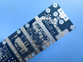
RO4003C exhibit a stable dielectric constant over a broad frequency range. This makes it an ideal substrate for broadband applications. And signal integrity performance improvement over the stack-ups with all FR4 board.
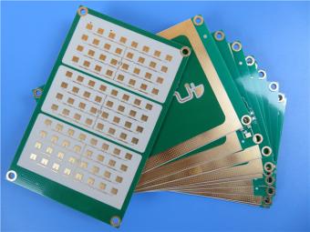
The hybrid PCB can be a mixture of FR-4 and high frequency material, and a mixture of high frequency material with different dielectric constant (DK)
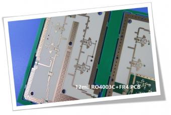
The 12mil core is on the top layer and it mainly plays the roles of signal layer. The core has fixed thickness which is very important to the electrical length of RF lines on the circuit board.
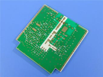
The hybrid PCB can be a mixture of FR-4 and high frequency material as abovementioned.
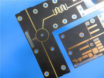
It contains 2 different boards in the panel. PCB boards are manufactured strictly as per required specifications with the standard IPC-Class-II.
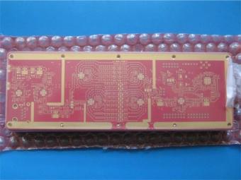
Hybrid PCB is also known as mixed material lamination, it’s normally combined by two different material like FR4 and PI(rigid flex PCB), FR4 and Ceramic, FR4 and Teflon, FR4 and Aluminum base etc.
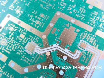
Hybrid constructions PCB typically involve a low loss material such as Nelco or Rogers combined with another core material like FR-4.
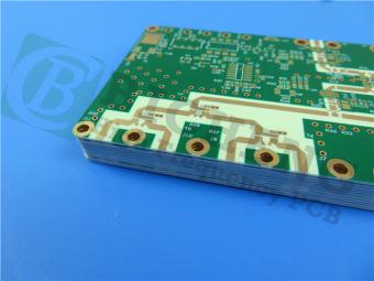
The Hybrid PCB on RO3003 and High Tg FR-4 is a state-of-the-art solution for high-frequency applications. With its exceptional stability, reliability, and manufacturability, it caters to the demands of industries such as automotive, telecommunications, and satellite communications.
 6-11C Shidai Jingyuan, Fuyong, Baoan, Shenzhen, Guangdong, China 518103


For inquiries about our products or pricelist, please leave to us and we will be in touch within 24 hours.
© Copyright: 2026 Shenzhen Bicheng Electronics Technology Co., Ltd.. All Rights Reserved.

IPv6 network supported
 -
-


