

 Call Us Now !
Tel : +86 755 27374946
Call Us Now !
Tel : +86 755 27374946
 Order Online Now !
Email : info@bichengpcb.com
Order Online Now !
Email : info@bichengpcb.com
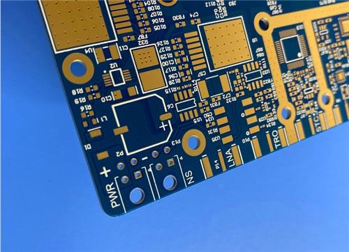
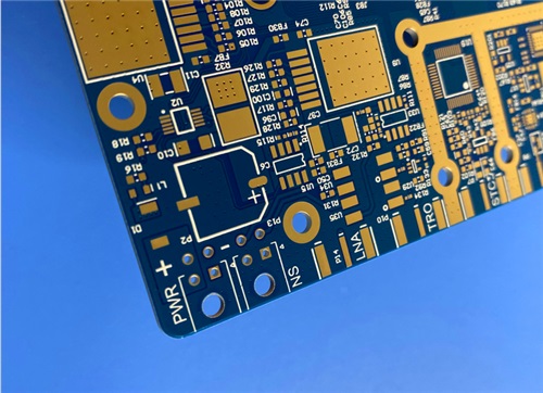
This 10-layer hybrid PCB integrates Rogers RO4003C high-frequency laminates and Isola 370HR high-thermal FR-4, designed for high‑reliability RF and high‑speed digital applications.
Item NO.:
BIC-570-v655.0Order(MOQ):
1-10Payment:
T/TProduct Origin:
ChinaShipping Port:
ShenzhenLead Time:
7-10 days
10-Layer Rogers RO4003C + 370HR FR4 Hybrid Laminate PCB ENIG Impedance Control
Product Overview
This product is a 10-layer hybrid printed circuit board (PCB) engineered for high-reliability, high-frequency RF/microwave and high-speed digital applications, combining Rogers RO4003C hydrocarbon-ceramic high-frequency laminates and Isola 370HR high-thermal-performance FR-4 multifunctional epoxy laminates into one integrated structure. It is purpose-built to satisfy demanding RF performance, thermal stability, mechanical robustness, and processing compatibility required in 5G wireless infrastructure, automotive radar, aerospace transceivers, base-station power amplifiers, and precision sensing systems.
The hybrid PCB stackup leverages the ultra-stable dielectric properties of RO4003C for RF signal paths and the superior thermal reliability, CAF resistance, and standard FR-4 processability of 370HR for digital control, power distribution, and multilayer lamination structures. With tightlycontrolled impedance,blind viastructures,resin-filled vias, immersion gold surface finish, and full-range electrical testing, thisHybridPCB delivers consistent electrical performance, excellent thermal cycling stability, strong chemical resistance, and long-term operational durability under harsh environmental conditions.
PCB Construction Details
This section summarizes the mechanical, material, structural, and surface finishing specifications of the10-layer hybrid board, with all parameters verified against IPC-A-600 Class 2/3 requirements and manufacturer datasheets.
|
Item |
Specification |
|
Base Material |
RO4003C + 370HR FR-4 hybrid laminate |
|
Layer Count |
10 copper layers |
|
Board Dimension |
132mm × 144mm (single piece), tolerance ±0.15mm |
|
Finished Board Thickness |
1.618mm |
|
Finished Copper Weight |
Outer layers: 1oz (35μm); Inner layers: mixed 1oz (35μm) & 0.5oz (18μm) |
|
Controlled Impedance |
Top layer (L1): 50Ω @ 12.2mil trace width; Layer 3: 80Ω @ 3.5mil trace width / 5.5mil spacing |
|
Via Type |
Blind vias: L1–L2, L9–L0, L7–L10 |
|
Special Process |
Resin-filled blind vias for planarization and reliability |
|
Surface Finish |
Immersion Gold (Au thickness: 135%–150% of standard specification) |
|
Solder Mask |
Top: Blue; Bottom: Blue |
|
Silkscreen |
Top: White legend; Bottom: White legend |
|
Quality Control |
100% electrical test before shipment |
PCB Stack-Up Structure
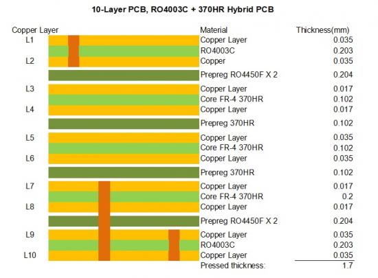
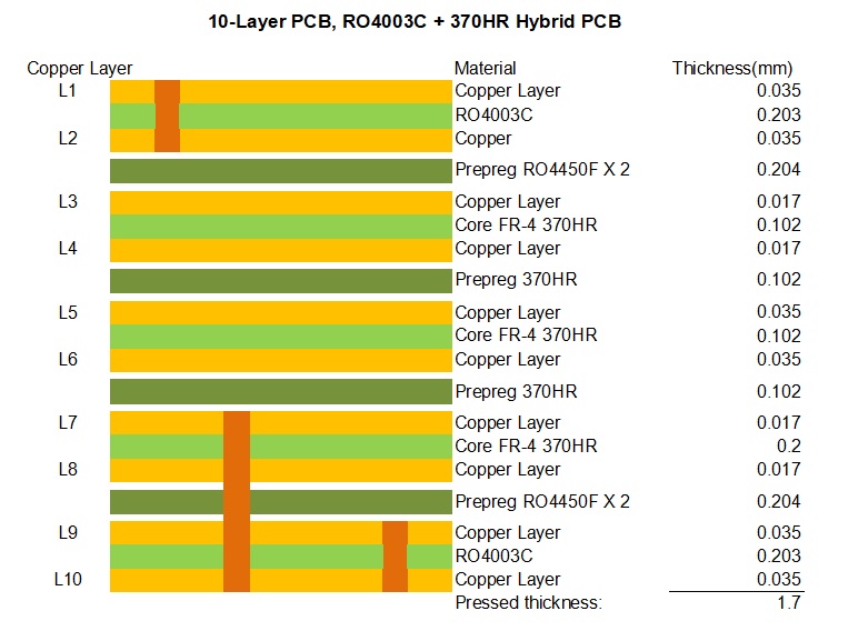
The following stack-up is designed to separate high-frequency RF layers (usingRogers4003C) from thermal/digital layers (using 370HR), minimize crosstalk, stabilize impedance, and reduce Z-axis thermal expansion. Layer order, dielectric thickness, copper weight, and material type are strictly controlled.
Key Performance Advantages
1. High-Frequency Signal Integrity
RO4003C provides stable Dk (3.38±0.05 @10GHz) and extremely low Df (0.0027 @10GHz), reducing insertion loss and phase distortion in RF paths. The dielectric constant remains stable across–50°C to 150°C, supporting broadband operation from 500MHz to 40GHz.
2. Superior Thermal Reliability
370HR features Tg 180°C, Td 340°C, T260≥60min, T288≥30min, and low CTE. It withstands lead-free reflow multiple times and resists CAF failure, ensuring long-term reliability in high-temperature environments.
3. Excellent Impedance Control
Precise dielectric thickness and trace geometry enable tight tolerance 50Ω/80Ωimpedance control, critical for impedance-matched RF circuits and high-speed links.
4. Advanced Structural Reliability
Blind vias reduce layer-to-layer stress; resin-filled vias improve planarity for SMT assembly. Low Z-axis CTE of both materials protects PTHs and vias during thermal cycling.
5. High Assembly Compatibility
Immersion gold provides stable, flat bonding surfaces; blue solder mask and white silkscreen improve inspection and rework. Materials support standard PCB and SMT processes.
6. Quality & Compliance
100% electrical test, IPC-4101/4103 compliance, RoHS, and UL recognition ensure consistent quality and regulatory acceptance.
Applications
This 10-layer hybrid PCB is ideal for:
It bridges the performance gap between pure high-frequency PCBs and standard FR-4 boards, offering an optimal balance of performance, reliability, processability, and cost.
CCL Material Knowledge Section
1. Rogers RO4003C High-Frequency Hydrocarbon-Ceramic Laminate
RO4003C is a non-PTFE, thermoset hydrocarbon-ceramic laminate designed for high-frequency RF/microwave circuits. It combines low loss, stable Dk, good thermal performance, and standard FR-4 process compatibility.
Key Characteristics
RO4003C Data sheet
|
Property |
Typical Value |
Tolerance / Condition |
Units |
Test Method |
|
Dielectric Constant (εᵣ) Process |
3.38 |
±0.05 @ 10GHz/23°C |
— |
IPC-TM-650 2.5.5.5 (Clamped Stripline) |
|
Design Dk (8-40 GHz) |
3.55 |
Average |
— |
Differential Phase Length |
|
Dissipation Factor (tan δ) |
0.0027 |
@ 10 GHz / 23°C |
— |
IPC-TM-650 2.5.5.5 |
|
Thermal Coefficient of εᵣ |
40 |
-50°C to 150°C |
ppm/°C |
IPC-TM-650 2.5.5.5 |
|
Volume Resistivity |
1.7×10¹⁰ |
COND A |
MΩ·cm |
IPC-TM-650 2.5.17.1 |
|
Surface Resistivity |
4.2×10⁹ |
COND A |
MΩ |
IPC-TM-650 2.5.17.1 |
|
Electrical Strength |
31.2 (780) |
0.51mm thickness |
kV/mm (V/mil) |
IPC-TM-650 2.5.6.2 |
|
Tensile Modulus (X) |
19,650 (2,850) |
RT |
MPa (ksi) |
ASTM D638 |
|
Tensile Modulus (Y) |
19,450 (2,821) |
RT |
MPa (ksi) |
ASTM D638 |
|
Coefficient of Thermal Expansion (X) |
11 |
-55 to 288°C |
ppm/°C |
IPC-TM-650 2.4.41 |
|
Coefficient of Thermal Expansion (Y) |
14 |
-55 to 288°C |
ppm/°C |
IPC-TM-650 2.4.41 |
|
Coefficient of Thermal Expansion (Z) |
46 |
-55 to 288°C |
ppm/°C |
IPC-TM-650 2.4.41 |
|
Tg (TMA) |
>280 |
— |
°C |
IPC-TM-650 2.4.24.3 |
|
Td (5% weight loss) |
425 |
— |
°C |
ASTM D3850 |
|
Thermal Conductivity |
0.71 |
@ 80°C |
W/m·K |
ASTM C518 |
|
Moisture Absorption |
0.06 |
48 hrs immersion |
% |
ASTM D570 |
|
Density |
1.79 |
@ 23°C |
g/cm³ |
ASTM D792 |
|
Copper Peel Strength |
1.05 (6.0) |
after solder float |
N/mm (pli) |
IPC-TM-650 2.4.8 |
|
Flammability |
N/A |
(Non-UL rated for FR) |
— |
UL 94 |
|
Lead-Free Process Compatible |
Yes |
— |
— |
— |
RO4003C Standard Thicknesses
Standard Panel Sizes
*Additional panel sizes available
Standard Claddings
*Additional cladding weights are available
2. Isola 370HR High-Thermal FR-4 Laminate & Prepreg
Isola 370HR is a high-performance multifunctional epoxy FR-4 system with a 180°C Tg, designed for high-thermal-reliabilitymultilayer PCBs that require superior thermal performance and conventional FR-4 processability.
Key Characteristics
Isola 370HR Data Sheet
|
Property |
Typical Values |
||||
|
|
Units |
Test Method |
|||
|
Typical |
Specification |
Metric |
IPC-TM-650 |
||
|
Value |
(English) |
(or as noted) |
|||
|
Glass Transition Temperature (Tg) by DSC |
180 |
170 |
ºC |
2.4.25 |
|
|
Decomposition Temperature (Td) by TGA @ 5% weight loss |
340 |
– |
ºC |
ASTM D3850 |
|
|
T260 |
60 |
– |
Minutes |
ASTM D3850 |
|
|
T288 |
30 |
– |
Minutes |
ASTM D3850 |
|
|
CTE, Z-axis |
A. Pre-Tg |
45 |
AABUS |
ppm/ºC |
2.4.24 |
|
B. Post-Tg |
230 |
– |
|||
|
CTE, X-, Y-axes |
A. Pre-Tg |
13/14 |
AABUS |
ppm/ºC |
2.4.24 |
|
B. Post-Tg |
14/17 |
– |
|||
|
Z-axis Expansion (50-260ºC) |
2.8 |
– |
% |
2.4.24 |
|
|
Thermal Conductivity |
0.4 |
– |
W/mK |
ASTM D5930 |
|
|
Thermal Stress 10 sec @ 288ºC (550.4ºF) |
A. Unetched |
Pass |
Pass Visual |
Rating |
|
|
B. Etched |
|||||
|
Dk, Permittivity |
A. @ 100 MHz (HP4285A) |
4.24 |
5.4 |
– |
2.5.5.3 |
|
(Laminate & prepreg as laminated) Tested at 50% resin |
B. @ 1 GHz (HP4291A) |
4.17 |
– |
2.5.5.9 |
|
|
C. @ 2 GHz (Bereskin Stripline) |
4.04 |
– |
2.5.5.5 |
||
|
D. @ 5 GHz (Bereskin Stripline) |
3.92 |
– |
2.5.5.5 |
||
|
E. @ 10 GHz (Bereskin Stripline) |
3.92 |
– |
2.5.5.5 |
||
|
Df, Loss Tangent |
A. @ 100 MHz (HP4285A) |
0.015 |
0.035 |
– |
2.5.5.3 |
|
(Laminate & prepreg as laminated) Tested at 50% resin |
B. @ 1 GHz (HP4291A) |
0.0161 |
– |
2.5.5.9 |
|
|
C. @ 2 GHz (Bereskin Stripline) |
0.021 |
– |
2.5.5.5 |
||
|
D. @ 5 GHz (Bereskin Stripline) |
0.025 |
– |
2.5.5.5 |
||
|
E. @ 10 GHz (Bereskin Stripline) |
0.025 |
– |
2.5.5.5 |
||
|
Volume Resistivity |
A. 96/35/90 |
– |
1.0x10⁶ |
MΩ-cm |
|
|
B. After moisture resistance |
3.0x10⁸ |
– |
|||
|
C. At elevated temperature |
7.0x10⁸ |
1.0x10³ |
|||
|
Surface Resistivity |
A. 96/35/90 |
– |
1.0x10⁴ |
MΩ |
|
|
B. After moisture resistance |
3.0x10⁶ |
– |
|||
|
C. At elevated temperature |
2.0x10⁸ |
1.0x10³ |
|||
|
Dielectric Breakdown |
>50 |
– |
kV |
2.5.6 |
|
|
Arc Resistance |
115 |
60 |
Seconds |
2.5.1 |
|
|
Electric Strength (Laminate & prepreg as laminated) |
54 (1350) |
30 (750) |
kV/mm |
2.5.6.2 |
|
|
(V/mil) |
|||||
|
Comparative Tracking Index (CTI) |
3 (175-249) |
– |
Class (Volts) |
UL-746A |
|
|
ASTM D3638 |
|||||
|
Peel Strength |
A. Low profile copper foil and very lowprofile – all copper weights >17 microns |
1.14 (6.5) |
0.70 (4.0) |
N/mm |
2.4.8 |
|
B. Standard profile copper |
– |
– |
2.4.8.2 |
||
|
1. After thermal stress |
1.25 (7.0) |
0.80 (4.5) |
2.4.8.3 |
||
|
2. At 125ºC (257ºF) |
1.25 (7.0) |
0.70 (4.0) |
– |
||
|
3. After process solutions |
1.14 (6.5) |
0.55 (3.0) |
– |
||
|
Flexural Strength |
A. Lengthwise direction |
90,000 |
– |
lb/inch2 |
2.4.4 |
|
B. Crosswise direction |
77,000 |
||||
|
Tensile Strength |
A. Lengthwise direction |
55,900 |
– |
lb/inch2 |
– |
|
B. Crosswise direction |
35,620 |
||||
|
Young's Modulus |
A. Grain direction |
3744 |
– |
ksi |
ww |
|
B. Fill direction |
3178 |
||||
|
Poisson's Ratio |
A. Grain direction |
0.177 |
– |
– |
xx |
|
B. Fill direction |
0.171 |
||||
|
Moisture Absorption |
0.15 |
– |
% |
2.6.2.1 |
|
|
Flammability (Laminate & prepreg as laminated) |
V-0 |
– |
Rating |
UL 94 |
|
|
Max Operating Temperature |
130 |
UL Cert |
ºC |
– |
|
|
The data, while believed to be accurate and based on analytical methods considered to be reliable, is for information purposes only. Any sales of these products will be governed by the terms and conditions of the agreement under which they are sold. |
|||||
Material Selection Logic for Hybrid PCB
Conclusion
This 10-layer hybrid PCB integrates Rogers RO4003C high-frequency laminates and Isola 370HR high-thermal FR-4, designed for high‑reliability RF and high‑speed digital applications. With a compact 132mm×144mm size and 1.618mm finished thickness, it features controlled 50Ω/80Ωimpedance, blind resin‑filled vias, 1oz outer and mixed 1oz/0.5oz inner copper, and immersion gold surface finish. Backed by RO4003C’s stable dielectric properties and 370HR’s excellent thermal reliability, the board delivers outstanding signal integrity and long‑term durability. Blue solder mask, white silkscreen, and 100% electrical testing ensure consistent quality. It is an ideal solution for 5G, automotive radar, aerospace, and precision RF systems.





Previous:
6-Layer RO4003C + FR4 Mixed Dielectric PCB with Hard Gold Plating Blind ViaNext:
4-Layer Rogers RO3003+TG170 FR-4 Hybrid PCB Immersion Silver Green Solder MaskIf you have questions or suggestions,please leave us a message,we will reply you as soon as we can!
Categories
New Products

Wangling F4BTMS220 2-Layer DK2.2 PCB 10 mil Core with Immersion Gold

Wangling F4BTME350 10mil DK3.5 High Frequency Substrate PCB 2-Layer Immersion Gold

Wangling F4BTM300 Custom 2-layer PCB 20mil DK3.0 Substrate with Immersion Gold

Rogers 20mil RT/duroid 6202 2-layer ENIG High-Frequency Microwave PCB

Rogers 20mil AD250C PCB Pure Gold High-Frequency Antenna Circuit Board

8-Layer Hybrid RF PCB: RO4350B + TG170 FR-4 + RO4003C with RO4450F Bondply

4-Layer Rogers RO3010 Hybrid PCB Immersion Silver 2.8mm Finished Thickness

4-Layer 20mil Rogers RO3210 ISIG High-Frequency PCB with Controlled Depth Milling
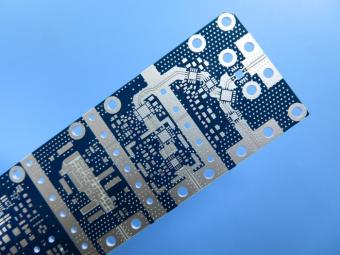
RO4003C exhibit a stable dielectric constant over a broad frequency range. This makes it an ideal substrate for broadband applications. And signal integrity performance improvement over the stack-ups with all FR4 board.
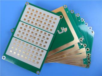
The hybrid PCB can be a mixture of FR-4 and high frequency material, and a mixture of high frequency material with different dielectric constant (DK)
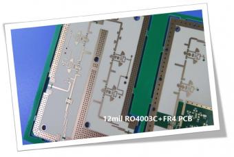
The 12mil core is on the top layer and it mainly plays the roles of signal layer. The core has fixed thickness which is very important to the electrical length of RF lines on the circuit board.
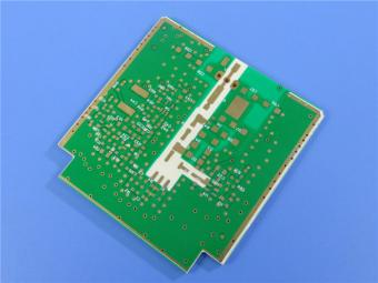
The hybrid PCB can be a mixture of FR-4 and high frequency material as abovementioned.
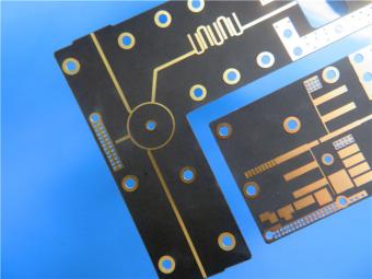
It contains 2 different boards in the panel. PCB boards are manufactured strictly as per required specifications with the standard IPC-Class-II.
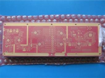
Hybrid PCB is also known as mixed material lamination, it’s normally combined by two different material like FR4 and PI(rigid flex PCB), FR4 and Ceramic, FR4 and Teflon, FR4 and Aluminum base etc.
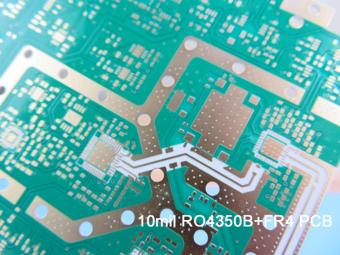
Hybrid constructions PCB typically involve a low loss material such as Nelco or Rogers combined with another core material like FR-4.
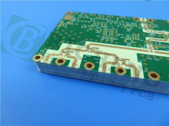
The Hybrid PCB on RO3003 and High Tg FR-4 is a state-of-the-art solution for high-frequency applications. With its exceptional stability, reliability, and manufacturability, it caters to the demands of industries such as automotive, telecommunications, and satellite communications.
 6-11C Shidai Jingyuan, Fuyong, Baoan, Shenzhen, Guangdong, China 518103


For inquiries about our products or pricelist, please leave to us and we will be in touch within 24 hours.
© Copyright: 2026 Shenzhen Bicheng Electronics Technology Co., Ltd.. All Rights Reserved.

IPv6 network supported


