

 Call Us Now !
Tel : +86 755 27374946
Call Us Now !
Tel : +86 755 27374946
 Order Online Now !
Email : info@bichengpcb.com
Order Online Now !
Email : info@bichengpcb.com

This 20mil RO4835 double-sided RF PCB achieves a balanced combination of stable high-frequency electrical performance, superior thermal oxidation resistance, cost-efficient FR-4 compatible fabrication and reliable immersion gold soldering surface.
Item NO.:
BIC-572-v657.0Order(MOQ):
1-10Payment:
T/TProduct Origin:
ChinaShipping Port:
ShenzhenLead Time:
7-10 days
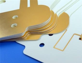
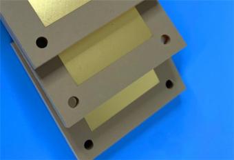
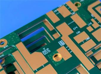
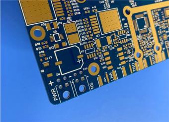
2-Layer 0.5mm TP440 PCB Wangling TP DK4.4 Laminate Immersion Gold
Product Overview
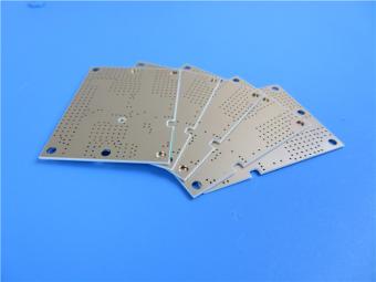
The 0.5mm TP440 PCB with Immersion Gold surface finish represents a specialized high-frequency circuit board solution engineered for demanding microwave and RF applications. Manufactured using Wangling's proprietary TP440 thermoplastic substrate material, this 2-layer Wangling PCB delivers exceptional dielectric performance, temperature stability, and mechanical reliability. Designed specifically for high-frequency operation up to 10 GHz, this Wangling TP DK4.4 Laminate PCB combines the unique properties of ceramic-filled PPO (Polyphenylene Oxide) resin with precision fabrication standards, making it an ideal choice for antenna systems, aerospace electronics, and miniaturized RF devices.
Unlike traditional FR-4 materials or ceramic substrates, the TP440 material PCB offers a unique balance of electrical performance, processability, and cost-effectiveness. The absence of fiberglass reinforcement, combined with precisely calibrated ceramic-PPO composite structure, enables consistent dielectric properties across wide frequency and temperature ranges. With a finished board thickness of 0.6mm and 1oz copper weight on both outer layers, this PCB provides robust signal integrity while maintaining a compact form factor of 67.5mm×58.6mm.
PCB Construction Details
The following table summarizes the critical construction specifications of the 2-layer TP440 PCB, outlining dimensional tolerances, feature capabilities, and manufacturing standards that define this high-frequency circuit board.
|
Parameter |
Specification |
|
Board Dimensions |
67.5mm × 58.6mm per unit, ±0.15mm |
|
Minimum Trace/Space |
6/8 mils |
|
Minimum Hole Size |
0.3mm |
|
Blind Vias |
None |
|
Finished Board Thickness |
0.6mm |
|
Finished Copper Weight |
1oz (35μm / 1.4 mils) outer layers |
|
Via Plating Thickness |
20μm |
|
Surface Finish |
Immersion Gold (ENIG) |
|
Top Silkscreen |
None |
|
Bottom Silkscreen |
None |
|
Top Solder Mask |
None |
|
Bottom Solder Mask |
None |
|
Electrical Test |
100% electrical test prior to shipment |
PCB Stackup Configuration
This 2-layer rigid PCB employs a symmetrical stackup design optimized for signal integrity and mechanical stability, utilizing the TP440 core material as the central dielectric layer.
|
Layer |
Material |
Thickness |
|
Layer 1 (Top) |
Copper |
35μm |
|
Core |
TP440 Dielectric |
0.5mm |
|
Layer 2 (Bottom) |
Copper |
35μm |
PCB Design Statistics
The following table provides a comprehensive breakdown of the PCB's design complexity metrics, including component count, pad distribution, via count, and net configuration.
|
Metric |
Value |
|
Components |
11 |
|
Total Pads |
19 |
|
Through-Hole Pads |
10 |
|
Top SMT Pads |
9 |
|
Bottom SMT Pads |
0 |
|
Vias |
7 |
|
Nets |
1 |
Key Differentiators and Application Suitability
1) Ultra-Low Dielectric Loss
Wangling TP440 achieves a dissipation factor (loss tangent) of 0.0010 at 10GHz—an exceptionally low value that minimizes signal attenuation in high-frequency transmission. While dielectric loss increases with frequency, the change remains insignificant within the 10GHz range, making TP440 highly suitable for applications operating in the L-band through X-band frequencies (1–10GHz). This low-loss characteristic is particularly critical for GPS antennas, missile-borne electronics, and fuze systems where signal integrity directly impacts system performance.
2) Precise and Stable Dielectric Constant
The dielectric constant of TP440 is precisely calibrated to 4.4 with a tight tolerance of±0.09. This level of precision—achieved through strict control of the ceramic-to-PPO resin ratio—ensures consistent electrical performance across all production batches. For engineers designing impedance-controlled transmission lines or resonant structures, this tight Dk tolerance translates to predictable, repeatable circuit performance without the need for extensive tuning or compensation.
Furthermore, the dielectric constant of TP series PCB materials can be customized within the range of 3 to 25 according to circuit requirements. Common values include 3.0, 4.4, 6.0, 6.15, 9.2, 9.6, 10.2, 11, 16, and 20—offering design flexibility for applications requiring specific dielectric constants beyond the standard 4.4 value.
3) Wide Operating Temperature Range
TP440 supports long-term operation from -100°C to +150°C with excellent low-temperature resistance. This broad temperature range makes the material suitable for aerospace, defense, and outdoor applications where extreme thermal environments are encountered. However, it is important to note that sustained temperatures above 180°C may cause material deformation, copper foil peeling, and significant changes in electrical performance—a critical consideration for assembly and rework processes.
4) Superior Mechanical and Processing Characteristics
Unlike ceramic substrates that require vacuum coating for copper adhesion, TP440’s copper foil exhibits more reliable adhesion to the dielectric layer. The material is readily machinable using conventional methods: drilling, turning, grinding, shearing, etching, and more—capabilities that ceramic substrates cannot achieve. This ease of processing translates to higher manufacturing yields and significantly lower fabrication costs compared to ceramic-based solutions.
5) Radiation Resistance and Low Outgassing
TP440 exhibits radiation resistance and low outgassing characteristics, making it suitable for space and aerospace applications where vacuum stability and radiation hardness are required. These properties are particularly valuable for satellite-borne and missile-borne electronics that must maintain performance in harsh radiation environments.
6) Application Domains
TP440 PCB is positioned as an ideal material for:
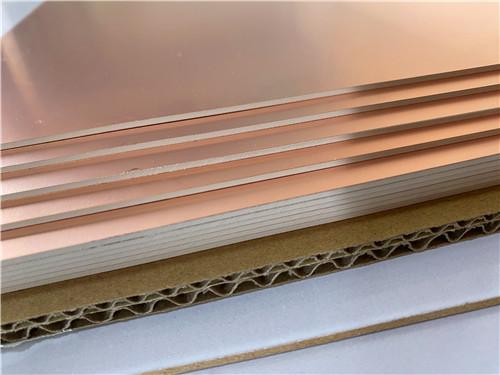
TP440 Copper Clad Laminate (CCL) Technical Datasheet
Material Introduction
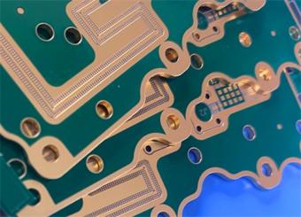
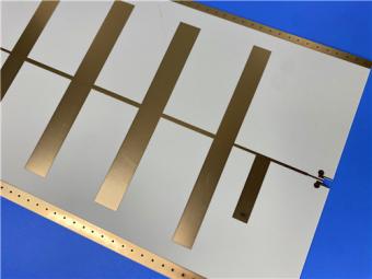
TP440 is a specializedhigh-frequency thermoplastic copper clad laminate manufactured by Wangling, representing a unique material innovation in the PCB industry. Unlike traditional fiberglass-reinforced laminates, TP440 utilizes a proprietary composite structure consisting of ceramic fillers uniformly dispersed in a Polyphenylene Oxide (PPO) resin matrix. This glass-free construction enables unprecedented control over dielectric properties while maintaining excellent mechanical processability.

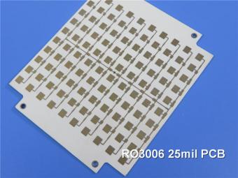
Figure:TP Series high-frequency copper clad laminate showing ceramic-PPO composite substrate with electrodeposited copper foil
The material is available in three configurations: TP (bare dielectric without copper cladding), TP-1 (single-sided copper clad), and TP-2 (double-sided copper clad). By precisely adjusting the ceramic-to-PPO resin ratio during manufacturing, the dielectric constant can be customized across an exceptionally wide range from 3.0 to 25, with TP440 specifically calibrated to Dk=4.4. This versatility enables engineers to select exact dielectric properties matched to their circuit requirements.
Complete Technical Specifications
The following table presents the complete technical specifications forTP440 PCB laminate, organized by property category with test conditions and corresponding values.
|
Test Item |
Test Condition |
Unit |
TP440 Typical Parameter |
|
Dielectric Constant (Dk) |
10GHz |
/ |
4.4 ± 0.09 |
|
Dielectric Constant Tolerance |
- |
% |
±2 |
|
Dissipation Factor (Df) |
10GHz |
/ |
0.001 |
|
Dielectric Constant Temperature Coefficient |
-55℃ ~ 150℃ |
PPM/℃ |
-50 |
|
Peel Strength (1oz copper) |
Normal state |
N/mm |
>0.6 |
|
Peel Strength (1oz copper) |
Alternating damp heat |
N/mm |
>0.4 |
|
Volume Resistivity |
Normal state, 500V |
MΩ·cm |
>1×10⁹ |
|
Surface Resistivity |
Normal state, 500V |
MΩ |
>1×10⁷ |
|
Coefficient of Thermal Expansion (X/Y/Z) |
-55℃ ~ 150℃ |
PPM/℃ |
60 / 60 / 70 |
|
Water Absorption |
20±2℃, 24h |
% |
≤0.01 |
|
Long-Term Operating Temperature |
Constant temperature test |
℃ |
-100 ~ +150 |
|
Density |
Room temperature |
g/cm³ |
1.89 |
|
Thermal Conductivity |
Room temperature |
W/(M·K) |
0.44 |
|
Material Composition |
- |
/ |
Ceramic + PPO resin + ED copper foil |
Material Features and Advantages
1). Precision Dielectric Control
The most significant advantage of TP440 lies in its exceptional dielectric consistency. With Dk=4.4±0.09 and tolerance of just±2%, this material provides the impedance control precision required for modern high-frequency designs. Unlike FR-4 materials which can exhibit Dk variations of±10% or more, TP440's tight tolerances ensure predictable circuit performance and minimize production tuning requirements.
2). Ultra-Low Signal Loss
With a dissipation factor of only 0.0010 at 10 GHz, TP440 delivers significantly lower insertion loss than conventional substrates. This low-loss characteristic is maintained across the entire operating frequency range up to 10 GHz, enabling efficient power transmission and maximizing signal-to-noise ratio in receiver applications.
3). Extreme Temperature Performance
Rated for continuous operation from -100°C to +150°C, TP440 excels in environments with extreme temperature variations. The material demonstrates particularly outstanding low-temperature performance, maintaining flexibility and electrical properties even at cryogenic temperatures. This makes it ideal for aerospace, defense, and polar region applications.
4). Superior Processability
Unlike brittle ceramic substrates that require specialized processing, TP440 can be fabricated using standard PCB manufacturing equipment. The material supports conventional drilling, routing, etching, and plating processes with high yields. Copper adhesion is significantly more reliable than vacuum-deposited metallization on ceramic substrates, reducing delamination risks and improving long-term reliability.
5). Environmental Resilience
TP440 exhibits excellent radiation resistance and extremely low outgassing, meeting the stringent requirements for space and high-vacuum applications. Water absorption of≤0.01% prevents moisture-induced dielectric shifts and ensures consistent performance in humid environments.
Standard Product Offerings
Copper Foil Specifications
- Type: Electrodeposited (ED) copper foil
- Standard Thicknesses: 0.018mm (½oz), 0.035mm (1oz)
Standard Panel Sizes
- 150×150 mm
- 160×160 mm
- 200×200 mm
- 170×240 mm
- Panel Size Tolerance: -2mm
Available Thickness Options (Dielectric or Total with Copper)
|
Standard Thickness (mm) |
Thickness Tolerance (mm) |
Standard Thickness (mm) |
Thickness Tolerance (mm) |
|
0.5 |
±0.04 |
4 |
±0.10 |
|
0.8 |
±0.05 |
5 |
±0.12 |
|
1 |
±0.05 |
6 |
±0.12 |
|
1.2 |
±0.05 |
7 |
±0.15 |
|
1.5 |
±0.06 |
8 |
±0.18 |
|
2 |
±0.075 |
10 |
±0.20 |
|
3 |
±0.10 |
12 |
±0.30 |
Note: Custom thicknesses available upon request. Please specify when ordering whether thickness refers to dielectric-only or total thickness including copper.
Dk Customization Options
The TP PCB laminate series offers a wide range of dielectric constants with corresponding tolerances
|
Model |
Dielectric Constant (Dk) |
Tolerance |
|
TP300 |
3 |
±0.06 |
|
TP440 |
4.4 |
±0.09 |
|
TP600 |
6 |
±0.12 |
|
TP615 |
6.15 |
±0.12 |
|
TP920 |
9.2 |
±0.18 |
|
TP960 |
9.6 |
±0.19 |
|
TP1020 |
10.2 |
±0.2 |
|
TP1100 |
11 |
±0.22 |
|
TP1600 |
16 |
±0.4 |
|
TP2000 |
20 |
±0.8 |
|
TP2200 |
22 |
±0.88 |
|
TP2500 |
25 |
±1.0 |
Custom dielectric constants between 3.0 and 25.0 are available upon request
Processing Guidelines and Recommendations
Soldering Considerations
- NOT recommended: 260°C thermal shock testing, wave soldering
- Recommended: Constant temperature soldering iron for manual assembly
- Reflow Soldering: Possible with maximum profile temperature≤200°C; thorough feasibility testing recommended
- Important: Material may deform, delaminate, or experience electrical property shifts at temperatures exceeding 180°C
Multilayer Construction
- Standard configuration: 2-layer rigid PCB (recommended)
- Multilayer constructions: Possible only with low-temperature bonding sheets; extensive feasibility evaluation required
- Not recommended for conventional multilayer PCB processing
Testing Standards
- Dielectric constant testing: GB/T 12636-1990 or IPC-TM650 [2.5.5.5](2.5.5.5) stripline method
- General performance: IPC-TM-650 or GB/T 4722-2017 test methods
- All values represent typical measured data for material selection guidance
Typical Applications
TP440 is the material of choice for:
- GPS and GNSS Antennas - Consistent dielectric properties ensure optimal antenna efficiency
- Missile-Borne Electronics - Extreme temperature and vibration resistance
- Fuze Systems - Reliable performance in harsh environmental conditions
- Miniaturized Antennas - High Dk enables compact antenna designs
- Beidou Navigation Systems - Precision performance for satellite communications
- Microwave Filters and Couplers - Low loss and stable Dk for filter applications
- Space Electronics - Radiation resistance and low outgassing characteristics
- High-Power RF Components - Good thermal conductivity and current carrying capacity
CCL Summary
TP440 microwave composite dielectric copper-clad laminate is a customized high-frequency substrate developed for professional microwave and extreme environment electronic devices. Its glass-fiber-free formula, adjustable dielectric system, ultra-low loss, wide temperature resistance and excellent machinability form obvious differentiation advantages compared with FR-4, ordinary PTFE and ceramic substrates. Complete thickness specifications, stable batch performance and clear processing guidelines enable it to support mass production of high-reliability PCBs. As the core raw material of the 0.5mm immersion gold PCB mentioned above, TP440 CCL determines the core performance ceiling of the finished PCB, and is a key foundational material for the long-term stable operation of navigation, aerospace and defense electronic equipment.


Previous:
Wangling TF300 25mil DK3.0 Laminate 2-layer PCB Immersion Gold Black SilkscreenNext:
WL-CT440 PCB 30mil 0.762mm Wangling Laminate ENIG Finish No Solder MaskIf you have questions or suggestions,please leave us a message,we will reply you as soon as we can!
Categories
New Products
Wangling TF300 25mil DK3.0 Laminate 2-layer PCB Immersion Gold Black Silkscreen
2-Layer 0.5mm TP440 PCB Wangling TP DK4.4 Laminate Immersion Gold
20-Layer Panasonic TU872 HDI PCB ENEPIG 3.0mm Finished Thick Laser-drilled Blind Vias
10-Layer Rogers RO4003C + 370HR FR4 Hybrid Laminate PCB ENIG Impedance Control
8-Layer 10oz Heavy Copper TU-865 Substrate PCB With ENIG Blind &Buried Via
4-Layer Rogers RO3210 + RO4450F PCB ISIG Surface Finish 1.321mm With Blind Via
4-Layer Rogers RO3003+TG170 FR-4 Hybrid PCB Immersion Silver Green Solder Mask
WL-CT440 PCB 30mil 0.762mm Wangling Laminate ENIG Finish No Solder Mask
Polytetrafluoroethylene (Short for PTFE), commonly known as "plastic king ", is a polymer compound made of tetrafluoroethylene by polymerization. It has excellent chemical stability, corrosion resistance, sealing, high lubrication and non-viscosity, electrical insulation and good aging resistance.
Rogers TMM4 thermoset microwave material is ceramic, hydrocarbon, thermoset polymer composite designed for high plated-through-hole reliability stripline and microstrip applications.
Taconic TLY laminates are a type of low loss laminates. They are manufactured with very light weight woven fiberglass and are more dimensionally stable than chopped fiber reinforced PTFE composites.
RO3203 laminates combine the surface smoothness of a non-woven PTFE laminate, for finer line etching tolerances, with the rigidity of a woven-glass PTFE laminate. These materials can be fabricated into printed circuit boards using
This type of immersion silver RF PCB is made on one of Taconic’s ORCER family material: RF-45.
Rogers’ TMM10 thermoset microwave materials are ceramic, hydrocarbon, thermoset polymer composites designed for high plated-thru-hole reliability stripline and microstrip applications.
Rogers RO3006 was designed to offer exceptional electrical and mechanical stability at competitive prices.
RT/duroid 6010LM microwave laminates feature ease of fabrication and stability in use. This property results in the possibility of mass production and reducing the cost of goods.
 6-11C Shidai Jingyuan, Fuyong, Baoan, Shenzhen, Guangdong, China 518103


For inquiries about our products or pricelist, please leave to us and we will be in touch within 24 hours.
© Copyright: 2026 Shenzhen Bicheng Electronics Technology Co., Ltd.. All Rights Reserved.

IPv6 network supported


