

 Call Us Now !
Tel : +86 755 27374946
Call Us Now !
Tel : +86 755 27374946
 Order Online Now !
Email : info@bichengpcb.com
Order Online Now !
Email : info@bichengpcb.com
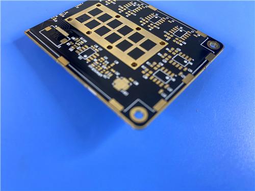
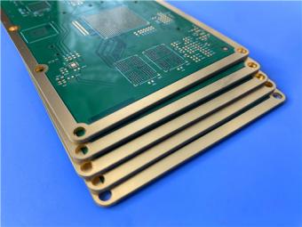
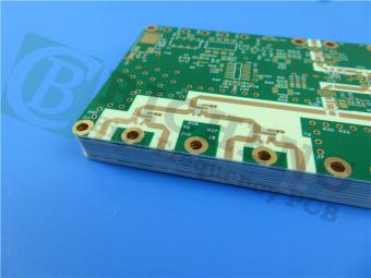
This 30mil TMM10i rigid PCB delivers a balanced engineering solution that resolves core pain points of traditional high-frequency circuit substrates.
Item NO.:
BIC-602-v687.0Order(MOQ):
1-10Payment:
T/TProduct Origin:
ChinaShipping Port:
ShenzhenLead Time:
7-10 days
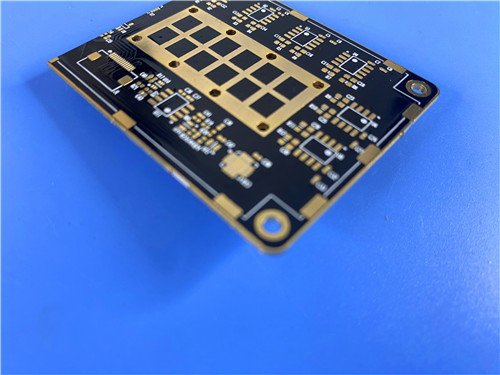
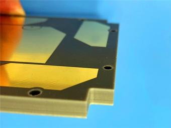
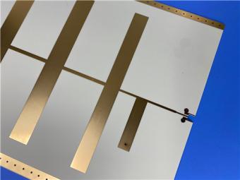
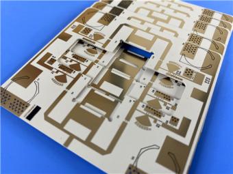
Rogers TMM10i PCB 30mil ENIG 2-layer Black Solder Mask with Edge Plating
Executive Summary
This product is a custom 2-layer rigid high-frequency printed circuit board built on Rogers TMM10i 30mil (0.762mm) thermoset ceramic-hydrocarbon composite core, finished with electroless nickel immersion gold (ENIG) surface treatment and manufactured to IPC-Class-2 industrial quality standards. Differentiated from conventional FR-4 and PTFE microwave PCBs, this TMM10i PCB integrates ultra-stable isotropic dielectric performance, copper-matched thermal expansion, simplified standard PCB manufacturability, and robust high-temperature mechanical stability. It eliminates the complex sodium napthanate surface activation mandatory for PTFE substrates, delivers consistent low RF loss across 8–40 GHz, and supports reliable through-hole plating, wire bonding, and lead-free reflow assembly.
Optimized for compact RF front-end hardware including satellite communication transceivers, GPS patch antennas, power combiners, and chip test fixtures, this two-sided board balances mass-production feasibility and high-frequency electrical precision without specialized exotic fabrication workflows.
The following content splits into independent PCB assembly specification section and standalone Rogers TMM10i CCL core material technical chapter, with dedicated summary conclusions after each module, standardized tabular parameter breakdowns, and full datasheet-backed material property data.
Part 1: PCB Complete Product Introduction
1.1 PCB Construction Parameter Overview
This table aggregates all mechanical, dimensional, surface finish and process constraints of the finished2-layer TMM10i PCB for rapid engineering review.
|
Parameter |
Specification |
|
Board Dimensions |
104.8mm × 99.01mm ± 0.15mm |
|
Minimum Trace/Space |
6/9 mils |
|
Minimum Hole Size |
0.4mm |
|
Blind Vias |
None |
|
Finished Board Thickness |
0.8mm |
|
Finished Copper Weight |
1 oz (1.4 mils) outer layers |
|
Via Plating Thickness |
20 μm |
|
Surface Finish |
ENIG (Electroless Nickel Immersion Gold) |
|
Top Silkscreen |
White |
|
Bottom Silkscreen |
White |
|
Top Solder Mask |
Black |
|
Bottom Solder Mask |
Black |
|
Edge Plating |
Yes |
|
Electrical Testing |
100% prior to shipment |
1.2 PCB Stackup Layer Structure Table
This table clarifies symmetrical double-sided copper stacking with TMM10i dielectric core as the intermediate isolation layer, defining exact thickness distribution of each conductive and dielectric layer.
|
Layer |
Material |
Thickness |
|
Layer 1 (Top Copper) |
Copper |
35 μm |
|
Core |
Rogers TMM10i |
0.762mm (30mil) |
|
Layer 2 (Bottom Copper) |
Copper |
35 μm |
1.3 PCB Component & Circuit Statistical Data Table
This quantitative table records all circuit feature counts of the sample PCB, providing reference for component placement density and interconnect complexity.
|
Parameter |
Quantity |
|
Components |
19 |
|
Total Pads |
52 |
|
Through-Hole Pads |
38 |
|
Top SMT Pads |
14 |
|
Bottom SMT Pads |
0 |
|
Vias |
18 |
|
Nets |
2 |
1.4 Core Differentiated Advantages of This TMM10i 2-Layer ENIG PCB
1) Dual advantage of ceramic stability & standard PCB processing
2) ENIG surface finish matched for high-frequency assembly & wire bonding
3) Thermal & mechanical reliability for wide-temperature working environments
4) Stable broadband low-loss electrical performance
1.5 Typical Application Scenarios for This PCB
The finished 2-layer TMM10i ENIG PCB is widely validated in commercial and industrial high-frequency hardware:
1.6 Conclusion of PCB Module
This 30mil TMM10i rigid PCB delivers a balanced engineering solution that resolves core pain points of traditional high-frequency circuit substrates: it combines the electrical stability of alumina ceramic, the process simplicity of standard FR-4 production, and the low-loss broadband characteristic of premium PTFE materials without their respective manufacturing limitations.
With standardized IPC-Class-2 quality control, precise fine-line routing capacity, full through-hole grounding design and ENIG high-reliability surface treatment, the board achieves consistent RF performance across full industrial temperature ranges while supporting scalable mass production. Its symmetrical two-layer stack-up minimizes impedance deviation and thermal stress, making it a cost-efficient replacement for single-sided PTFE boards and fragile thick-film ceramic substrates in medium-power microwave communication equipment.
Part 2: Rogers TMM10i CCL Core Laminate In-Depth Material Explanation
2.1 Material Basic Definition & Composition
Rogers TMM10i is a proprietary thermoset microwave composite CCL manufactured by Rogers Corporation, constructed from hydrocarbon thermoset polymer matrix uniformly filled with high-purity ceramic powder, clad with electrodeposited copper foil. It belongs to the TMM series isotropic thermoset substrate family, engineered specifically for stripline and microstrip circuits requiring high plated through-hole reliability.
Its hybrid material formula integrates the low-loss dielectric property of ceramic fillers and the formability, chemical resistance and non-thermoplastic characteristic of cross-linked hydrocarbon resin. Unlike thermoplastic substrates, TMM10i will not soften, creep or cold flow under sustained high operating temperature or mechanical load, eliminating pad lifting during wire bonding and reflow assembly.
2.2 Full Datasheet Technical Property Table of TMM10i Laminate
All data below are extracted from official Rogers 2022 revision datasheet (Publication #92-108), test standards and tolerance ranges fully compliant with IPC and ASTM international testing specifications.
|
Property Category |
Test Item |
Typical TMM10i Value |
Test Direction |
Unit |
Test Condition |
Standard Test Method |
|
Electrical Properties |
Process Dielectric Constant Dk |
9.80 ±0.245 |
Z-axis |
- |
10 GHz |
IPC-TM-650 2.5.5.5 |
|
Design Dielectric Constant Dk |
9.9 |
Bulk |
- |
8–40 GHz |
Differential Phase Length Method |
|
|
Dissipation Factor Df |
0.002 |
Z-axis |
- |
10 GHz |
IPC-TM-650 2.5.5.5 |
|
|
Thermal Coefficient of Dk (TCDk) |
-43 |
Bulk |
ppm/°K |
-55°C ~ +125°C |
IPC-TM-650 2.5.5.5 |
|
|
Insulation Resistance |
>2000 |
Bulk |
GΩ |
C/96/60/95 |
ASTM D257 |
|
|
Volume Resistivity |
2×10⁸ |
Bulk |
MΩ·cm |
Room temp |
ASTM D257 |
|
|
Surface Resistivity |
4×10⁷ |
Bulk |
MΩ |
Room temp |
ASTM D257 |
|
|
Dielectric Strength |
267 |
Z-axis |
V/mil |
Room temp |
IPC-TM-650 2.5.6.2 |
|
|
Thermal Properties |
Decomposition Temperature Td |
425 |
Bulk |
°C |
TGA heating |
ASTM D3850 |
|
CTE X-axis |
19 |
X |
ppm/K |
0–140°C |
ASTM E831 / IPC-TM-650 2.4.41 |
|
|
CTE Y-axis |
19 |
Y |
ppm/K |
0–140°C |
ASTM E831 / IPC-TM-650 2.4.41 |
|
|
CTE Z-axis |
20 |
Z |
ppm/K |
0–140°C |
ASTM E831 / IPC-TM-650 2.4.41 |
|
|
Thermal Conductivity |
0.76 |
Z-axis |
W/m/K |
80°C |
ASTM C518 |
|
|
Mechanical & Assembly Properties |
Copper Peel Strength (1oz Cu after thermal stress) |
5.0 (0.9) |
X/Y |
lb/in (N/mm) |
Solder float test |
IPC-TM-650 2.4.8 |
|
Flexural Modulus |
1.80* |
X/Y |
Mpsi |
Standard A condition |
ASTM D790 |
|
|
Moisture Absorption (0.050” thickness) |
0.16 |
Bulk |
% |
D/24/23 |
ASTM D570 |
|
|
Moisture Absorption (0.125” thickness) |
0.13 |
Bulk |
% |
D/24/23 |
ASTM D570 |
|
|
Specific Gravity |
2.77 |
Bulk |
- |
Standard A condition |
ASTM D792 |
|
|
Specific Heat Capacity |
0.72* |
Bulk |
J/g/K |
Calculated value |
N/A |
|
|
Process Compatibility |
Lead-Free Process Compatible |
YES |
- |
- |
Lead-free reflow peak temp |
N/A |
*Note: Marked asterisk data are estimated typical values for engineering reference; certified specification data available upon request to Rogers Corporation. Prolonged oxidation environment exposure may slightly alter dielectric parameters, design validation under full product lifecycle temperature cycling is recommended by the material manufacturer.
2.3 Standard Available Specifications of TMM10i Raw CCL
1) Core dielectric thickness range:
2) Standard copper cladding options:
3) Standard panel sheet dimensions:
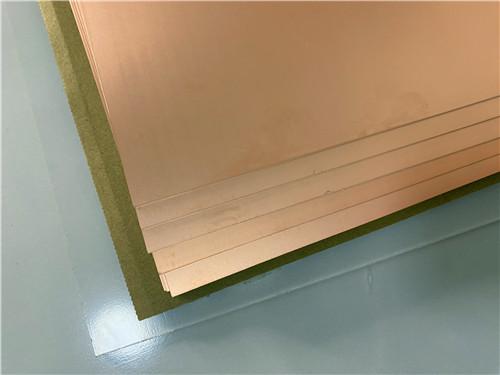
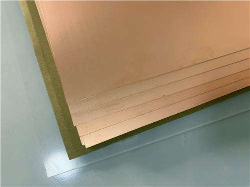
Raw Rogers TMM10i Copper-Clad Laminate Sheet
2.4 Unique Differentiating Material Characteristics of TMM10i vs Competitive Substrates
1) No mandatory pre-plating surface activation treatment
2) Isotropic dielectric constant with low TCDk for wide temperature stability
3) Thermoset non-melting matrix enables reliable wire bonding
4) Balanced thermal conductivity and CTE matching to copper for PTH reliability
5) Direct substitute for alumina ceramic substrates with lower processing cost
2.5 CCL Material Conclusion
Rogers TMM10i thermoset ceramic-hydrocarbon copper-clad laminate fills the performance gap between low-cost unstable FR-4, high-processing-cost PTFE substrates and rigid but hard-to-machine alumina ceramics. Its integrated advantages of isotropic low-loss broadband dielectric performance, copper-matched thermal expansion, doubled thermal conductivity versus conventional PTFE composites, lead-free assembly compatibility, and full standard PCB process adaptability make it the optimal core dielectric material for this30mil2-layer ENIG RF PCB.
The complete set of standardized electrical, thermal, mechanical data from official datasheets delivers fully predictable design parameters for RF circuit engineers, while eliminating numerous complex, costly pre-treatment steps required by alternative high-frequency substrates. For commercial satellite, GPS, power amplifier and semiconductor test applications requiring consistent microwave performance across wide temperature ranges, TMM10i CCL provides a balanced high-reliability and cost-effective substrate solution without performance compromises.





Previous:
2-Layer 20mil Rogers TMM13i with ENIG Finish High-Frequency Microwave Circuit BoardNext:
RO3006 PCB 5mil Rogers Substrate 2-layer ENIG Finish No Solder maskIf you have questions or suggestions,please leave us a message,we will reply you as soon as we can!
Categories
New Products

8-Layer Hybrid RF PCB: RO4350B + TG170 FR-4 + RO4003C with RO4450F Bondply

4-Layer Rogers RO3010 Hybrid PCB Immersion Silver 2.8mm Finished Thickness

4-Layer 20mil Rogers RO3210 ISIG High-Frequency PCB with Controlled Depth Milling
4-Layer 10mil RO3003 + Tg170 FR-4 Hybrid PCB with ENIG and Controlled Depth Milling
2-Layer F4BM233 4.0mm Wangling Substrate High-Frequency Custom PCB with ENIG Finish
Wangling WL-CT615 8mil Ultra-Thin High-Frequency 2-Layer PCB ENEPIG Finish
High-Frequency 2-Layer PCB on 59mil Wangling TP440 Thermoplastic Dielectric Immersion Gold
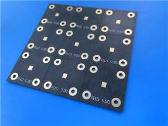
AGC Taconic TLX-6 PTFE Fiberglass Laminate PCB 2-layer 3.5mil ENIG Finish
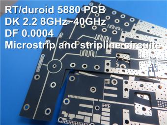
This is a type of double sided RF PCB built on RT/duroid 5880 for the application of Radar Systems.
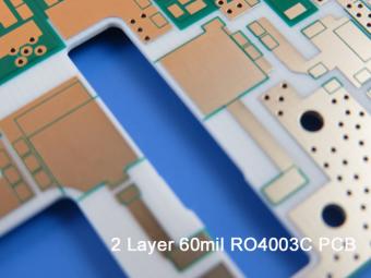
RO4003C PCBs are hydrocarbon ceramic filled laminates, not PTFE which are designed to offer superior high frequency performance.
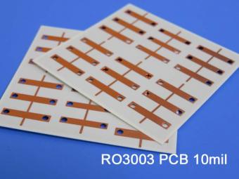
Rogers RO3003 high frequency circuit materials are ceramic-filled PTFE composites intended for use in commercial microwave and RF applications. It was designed to offer exceptional electrical and mechanical stability at competitive prices.
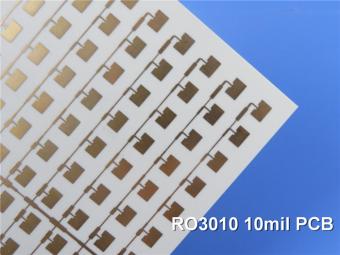
RO3010 laminates are competitively priced products with exceptional mechanical and electrical stability. This stability simplifies the design of broadband components and allows the materials to be used in a wide range of applications over a very broad range of frequencies.
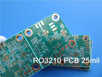
These RO3210 materials are engineered to offer exceptional electrical performance and mechanical stability. RO3210 laminates combine the surface smoothness of a non-woven PTFE laminate.
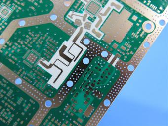
RT/duroid 6035HTC laminates are an exceptional choice for high power applications.
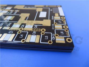
TC350 is designed to provide enhanced heat-transfer through “Best-In-Class” thermal conductivity, while reducing dielectric loss and insertion loss. Lower losses result in higher Amplifier and Antenna Gains/Efficiencies.
RO3035 materials exhibit a coefficient of thermal expansion(CTE) in the X and Y axis of 17 ppm/℃. This expansion coefficient is matched to that of copper, which allows the material to exhibit excellent dimensional stability.
 6-11C Shidai Jingyuan, Fuyong, Baoan, Shenzhen, Guangdong, China 518103


For inquiries about our products or pricelist, please leave to us and we will be in touch within 24 hours.
© Copyright: 2026 Shenzhen Bicheng Electronics Technology Co., Ltd.. All Rights Reserved.

IPv6 network supported


