

 Call Us Now !
Tel : +86 755 27374946
Call Us Now !
Tel : +86 755 27374946
 Order Online Now !
Email : info@bichengpcb.com
Order Online Now !
Email : info@bichengpcb.com
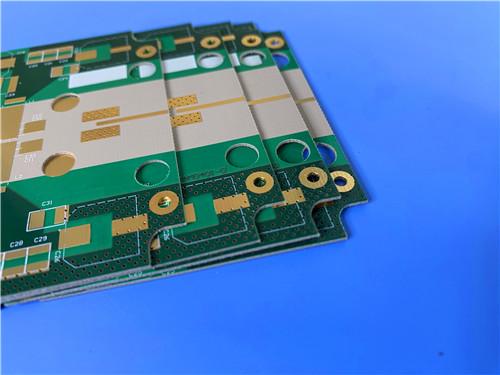
This 20mil Rogers 6202 PCB with ENIG finish is a purpose-engineered high-frequency microwave solution.
Item NO.:
BIC-626-v711Order(MOQ):
1-10Payment:
T/TProduct Origin:
ChinaShipping Port:
ShenzhenLead Time:
7-10 days
Rogers 20mil RT/duroid 62022-layer ENIG High-Frequency Microwave PCB
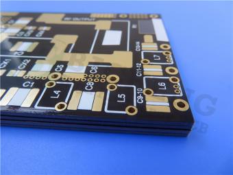
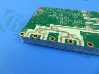
Thisarticle presents a 2-layer rigid PCB fabricated onRogers RT/duroid 6202 high-frequency laminate with ENIG surface finish. At 0.6 mm finished thickness built on a 20 mil (0.508 mm) dielectric core, theRogersboard measures 42.36 by 21.9 mm and is engineered for microwave and radar applications requiring low insertion loss and exceptional electrical stability. The following sections detail the PCB construction, stackup, design statistics, performance differentiation, and applications, followed by an in-depth technical review of theRT/duroid 6202 copper-clad laminate material.
The 20mil RT/duroid 6202 PCB is a 2-layer rigid high-frequency circuit board measuring 42.36 by 21.9 mm, yielding one piece per panel array. Built on Rogers' limited woven glass-reinforced PTFE composite, it carries 1 oz (35 um, approximately 1.4 mils) copper on both outer layers and an ENIG (Electroless Nickel Immersion Gold) surface finish. The finished board thickness is 0.6 mm, centered on a 20 mil (0.508 mm) RT/duroid 6202 dielectric core.
The table below summarizes the complete construction specifications, covering base material, layer count, dimensional tolerances, copper weight, surface finish, and quality acceptance criteria.
|
Parameter |
Specification |
|
Base Material |
RT/duroid 6202 |
|
Layer Count |
2-layer rigid |
|
Board Dimensions |
42.36 x 21.9 mm (1 PCS) |
|
Min Trace / Space |
4 / 7 mils |
|
Min Hole Size |
0.4 mm |
|
Via Type |
Through-hole only (no blind vias) |
|
Finished Thickness |
0.6 mm |
|
Finished Cu Weight |
1 oz (1.4 mils / 35 um) outer layers |
|
Via Plating Thickness |
20 um |
|
Surface Finish |
ENIG (Electroless Nickel Immersion Gold) |
|
Top Silkscreen |
White |
|
Bottom Silkscreen |
None |
|
Top Solder Mask |
Green |
|
Bottom Solder Mask |
None |
|
Electrical Test |
100% prior to shipment |
|
Artwork Format |
Gerber RS-274-X |
|
Quality Standard |
IPC-Class-2 |
|
Availability |
Worldwide |
A symmetric 2-layer stackup is centered on a 20 mil RT/duroid 6202 core with 35 um electrodeposited copper on both top and bottom layers, ensuring balanced thermal expansion and consistent impedance control.
|
Layer |
Material |
Thickness |
|
Copper Layer 1 (Top) |
Electrodeposited Copper (1 oz) |
35 um (1.4 mils) |
|
Core Substrate |
Rogers RT/duroid 6202 |
0.508 mm (20 mils) |
|
Copper Layer 2 (Bottom) |
Electrodeposited Copper (1 oz) |
35 um (1.4 mils) |
The design comprises 13 components, 20 total pads (11 through-hole and 9 top-side SMT), 6 through-hole vias, and 2 electrical nets, reflecting a compact, high-density microwave circuit layout.
|
Metric |
Count |
|
Components |
13 |
|
Total Pads |
20 |
|
Through-Hole Pads |
11 |
|
Top SMT Pads |
9 |
|
Bottom SMT Pads |
0 |
|
Vias |
6 |
|
Nets |
2 |
RT/duroid 6202 high frequency PCB is distinguished by its tightly controlled dielectric constant of 2.94 +/- 0.04 at 10 GHz and 23 degrees Celsius for laminate thicknesses of 0.020 inch and above, placing it among the lowest-Dk glass-reinforced high-frequency materials in the Rogers portfolio. This low Dk, combined with a dissipation factor of just 0.0015 at 10 GHz, minimizes phase velocity variation and insertion loss in microwave signal paths, making it particularly valuable for wideband antenna and radar feed networks. The thermal coefficient of dielectric constant is exceptionally low at +5 ppm/degree Celsius over the range of -50 to +150 degrees Celsius, ensuring that resonant frequencies, phase shifts, and characteristic impedance remain stable across extreme operating temperatures. This is a critical advantage for ground-based and airborne radar systems deployed in harsh thermal environments, where competing materials with higher TCDk values (typically 20 to 50 ppm/degree Celsius) would exhibit noticeable frequency drift.
Unlike pure PTFE laminates such as RT/duroid 5880, RT/duroid 6202 incorporates limited woven glass reinforcement, yielding dimensional stability of 0.05 to 0.07 mils per inch after etch and bake cycles. This often eliminates the need for double etching to achieve tight positional tolerances, improving manufacturing yield and reducing production cost. The in-plane coefficient of thermal expansion is 15 ppm/degree Celsius in both X and Y axes, closely matching copper's 17 ppm/degree Celsius and minimizing thermally induced shear stress on plated through holes and copper traces during assembly reflow and field operation. With a decomposition temperature (Td) of 500 degrees Celsius by TGA and thermal conductivity of 0.68 W/m/K at 80 degrees Celsius, the material withstands lead-free reflow profiles and dissipates heat effectively in power-dense circuits. Moisture absorption of only 0.04 percent ensures that electrical properties remain stable under humid conditions, and the UL 94 V-0 flammability rating meets stringent safety requirements for commercial and aerospace applications.
The ENIG surface finish further differentiates this board by offering a flat, coplanar contact surface with excellent shelf life and consistent contact resistance, avoiding the tin whisker risk and surface non-planarity associated with HASL finishes. The nickel layer under the immersion gold provides a robust barrier against copper diffusion, while the gold layer ensures solderability and oxidation resistance. At 9.1 lbs per inch (1.6 N/mm) copper peel strength, the laminate ensures robust copper-to-dielectric adhesion under thermal cycling and mechanical stress. The combination of low Dk, ultra-low Df, temperature-stable electrical properties, copper-matched CTE, and excellent dimensional stability positions RT/duroid 6202 as a premium choice for high-reliability microwave circuits where electrical performance and manufacturing consistency are equally critical.
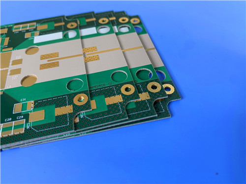
The 20mil RT/duroid 6202 PCB ENIG finish is well suited for:
The low Dk and ultra-low Df make it particularly suited for wideband microwave components where signal integrity, phase accuracy, and low insertion loss govern overall system performance. Its compact 42.36 by 21.9 mm form factor and 2-layer construction also make it appropriate for size-constrained RF modules, satellite communication front-ends, and test and measurement fixtures requiring stable, repeatable high-frequency characteristics.
This 20mil Rogers 6202 PCB with ENIG finish is a purpose-engineered high-frequency microwave solution. A low-loss PTFE-glass composite substrate, 4/7 mil trace geometry, 1 oz copper construction, 20 um via plating, 100 percent electrical testing, and IPC-Class-2 quality assurance combine to deliver reliable electrical performance in a compact 42.36 by 21.9 mm form factor.
The material's copper-matched CTE, exceptional dimensional stability, temperature-stable Dk of 2.94 +/- 0.04, and ultra-low dissipation factor of 0.0015 ensure long-term reliability and consistent performance in demanding radar, phased array, and beam-forming environments. With worldwide availability and proven lead-free process compatibility, this PCB represents a high-value, high-performance solution for engineers seeking a balance of electrical excellence and manufacturing robustness.
Rogers RT/duroid 6202 laminate is a high-frequency circuit material engineered as a low-loss, low-dielectric-constant laminate with limited woven glass reinforcement. It is designed to provide the electrical and mechanical properties essential for designing complex microwave structures that are both mechanically reliable and electrically stable.
The material is part of Rogers RT/duroid family, which has been a benchmark in the high-frequency PCB industry for decades. RT/duroid 6202 occupies a unique position in the portfolio: it offers a Dk of 2.94 for standard thicknesses of 0.020 inch and above, lower than many glass-reinforced competitors but with superior dimensional stability compared to unreinforced PTFE laminates, making it ideal for designs that balance electrical performance with manufacturability and registration accuracy.
RT/duroid 6202 is a PTFE (polytetrafluoroethylene) composite reinforced with a limited amount of woven glass fiber. The PTFE matrix provides inherently low dielectric loss, excellent chemical resistance, and high thermal stability. The woven glass reinforcement, deliberately limited in quantity to avoid elevating the dielectric constant, improves dimensional stability, mechanical handling, and registration accuracy during PCB fabrication. This hybrid construction addresses a key limitation of unreinforced PTFE laminates, which tend to exhibit greater etch shrinkage and dimensional movement during processing.
The result is a material that retains the electrical benefits of PTFE while approaching the dimensional stability of glass-reinforced epoxy laminates. Excellent dimensional stability of 0.05 to 0.07 mils per inch is achieved through this limited woven glass reinforcement, which often eliminates the need for double etching to achieve tight positional tolerances. The copper cladding is available in both electrodeposited (ED) and rolled foil formats, with standard weights of half oz (18 um) and 1 oz (35 um), providing flexibility for different current-carrying and conductor-loss requirements. The material is fully compatible with lead-free assembly processes and carries a UL 94 V-0 flammability rating.
The full datasheet below covers electrical, thermal, mechanical, and physical properties. All values are typical at 23 degrees Celsius unless otherwise noted; SI units are given first with other frequently used units in parentheses. Dielectric constant varies by laminate thickness due to construction limitations.
|
Property |
Value |
Direction |
Units |
Conditions |
Test Method |
|
Electrical |
|||||
|
Dielectric Constant (Dk) |
2.94 +/- 0.04 [a] |
Z |
- |
10 GHz / 23 C |
IPC-TM-650 2.5.5.5 |
|
Dissipation Factor (Df) |
0.0015 |
Z |
- |
10 GHz / 23 C |
IPC-TM-650 2.5.5.5 |
|
Thermal Coeff. of Dk |
+5 |
Z |
ppm/C |
10 GHz, -50 to +150 C |
IPC-TM-650 2.5.5.5 |
|
Volume Resistivity |
10^6 |
Z |
Mohm-cm |
Condition A |
ASTM D257 |
|
Surface Resistivity |
10^9 |
Z |
Mohm |
Condition A |
ASTM D257 |
|
Thermal |
|||||
|
Thermal Conductivity |
0.68 |
- |
W/m/K |
80 C |
ASTM C518 |
|
CTE (-55 to 288 C) |
15 / 15 / 30 |
X / Y / Z |
ppm/C |
23 C / 50% RH |
IPC-TM-650 2.4.41 |
|
Decomposition Temp (Td) |
500 |
- |
C (TGA) |
- |
ASTM D3850 |
|
Specific Heat |
0.93 (0.22) |
- |
J/g/K (BTU/lb/F) |
- |
Calculated |
|
Lead-Free Process Compatible |
YES |
- |
- |
- |
- |
|
Mechanical |
|||||
|
Tensile Modulus |
1007 (146) |
X, Y |
MPa (kpsi) |
23 C |
ASTM D638 |
|
Ultimate Stress |
30 (4.3) |
X, Y |
MPa (kpsi) |
23 C |
ASTM D638 |
|
Ultimate Strain |
4.9 |
X, Y |
% |
23 C |
ASTM D638 |
|
Compressive Modulus |
1035 (150) |
Z |
MPa (kpsi) |
- |
ASTM D638 |
|
Copper Peel Strength |
9.1 (1.6) |
- |
lbs/in (N/mm) |
- |
IPC-TM-650 2.4.8 |
|
Dimensional Stability |
0.07 |
X, Y |
mm/m (mil/inch) |
after etch + E/150 |
IPC-TM-650 2.4.3.9 |
|
Physical |
|||||
|
Moisture Absorption |
0.04 |
- |
% |
D23/24, D48/50 |
IPC-TM-650 2.6.2.1 / ASTM D570 |
|
Density |
2.1 |
- |
g/cm3 |
- |
ASTM D792 |
|
Flammability |
V-0 |
- |
- |
- |
UL 94 |
[a] Due to construction limitations, the dielectric constant of 0.005 inch laminates is 3.06 +/- 0.04; 0.010 inch and 0.015 inch laminates are 3.02 +/- 0.04; and laminates of 0.020 inch and greater are 2.94 +/- 0.04, all measured at 10 GHz and 23 degrees Celsius.
Three standard dielectric thicknesses are available with matching panel sizes and copper cladding options. Additional non-standard thicknesses from 0.005 to 0.060 inch, alternate panel sizes, and special claddings such as resistive foil and reverse-treated ED copper are available upon request.
|
Standard Thicknesses |
Standard Panel Sizes |
Standard Claddings |
|
0.005" (0.127 mm) +/- 0.0005" 0.020" (0.508 mm) +/- 0.0010" 0.030" (0.762 mm) +/- 0.0010" |
12" x 18" (305 x 457 mm) 24" x 18" (610 x 457 mm) |
ED Copper Foil: 1/2 oz (18 um) HH/HH 1 oz (35 um) H1/H1 Rolled Copper Foil: 1/2 oz (18 um) 5R/5R 1 oz (35 um) 1R/1R |

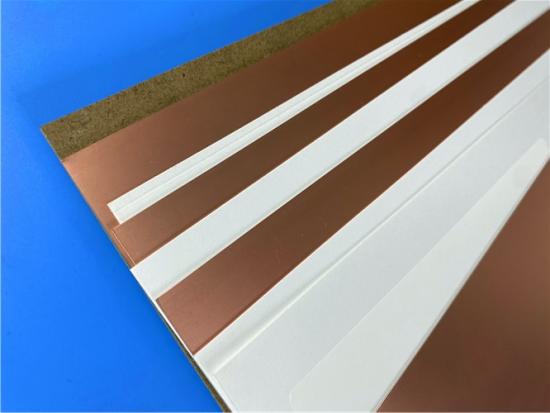
Figure 1: RT/duroid 6202 copper-clad laminate showing electrodeposited copper foil and PTFE-glass dielectric layers.
Rogers RT/duroid 6202 is a purpose-engineered high-frequency laminate that combines the ultra-low loss of PTFE with the dimensional stability and handling robustness of limited woven glass reinforcement. Its tightly controlled dielectric constant of 2.94 +/- 0.04 at 10 GHz for thicknesses of 0.020 inch and above, ultra-low dissipation factor of 0.0015, exceptional temperature stability of +5 ppm/degree Celsius TCDk, and copper-matched in-plane CTE of 15 ppm/degree Celsius make it an excellent substrate for phased array antennas, ground-based and airborne radar systems, GPS antennas, beam forming networks, and commercial airline collision avoidance systems.
With a comprehensive property set spanning electrical, thermal, mechanical, and physical domains, three standard thicknesses, multiple panel sizes, both ED and rolled copper cladding options, and proven lead-free process compatibility with UL 94 V-0 certification, RT/duroid 6202 offers designers a reliable, high-performance, and manufacturable substrate for the most demanding microwave and millimeter-wave applications.





If you have questions or suggestions,please leave us a message,we will reply you as soon as we can!
Categories
New Products

Rogers 20mil RT/duroid 6202 2-layer ENIG High-Frequency Microwave PCB

Rogers 20mil AD250C PCB Pure Gold High-Frequency Antenna Circuit Board

8-Layer Hybrid RF PCB: RO4350B + TG170 FR-4 + RO4003C with RO4450F Bondply

4-Layer Rogers RO3010 Hybrid PCB Immersion Silver 2.8mm Finished Thickness

4-Layer 20mil Rogers RO3210 ISIG High-Frequency PCB with Controlled Depth Milling
4-Layer 10mil RO3003 + Tg170 FR-4 Hybrid PCB with ENIG and Controlled Depth Milling
2-Layer F4BM233 4.0mm Wangling Substrate High-Frequency Custom PCB with ENIG Finish
Wangling WL-CT615 8mil Ultra-Thin High-Frequency 2-Layer PCB ENEPIG Finish
This is a type of double sided RF PCB built on RT/duroid 5880 for the application of Radar Systems.
RO4003C PCBs are hydrocarbon ceramic filled laminates, not PTFE which are designed to offer superior high frequency performance.
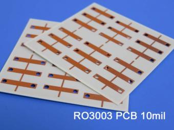
Rogers RO3003 high frequency circuit materials are ceramic-filled PTFE composites intended for use in commercial microwave and RF applications. It was designed to offer exceptional electrical and mechanical stability at competitive prices.
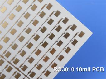
RO3010 laminates are competitively priced products with exceptional mechanical and electrical stability. This stability simplifies the design of broadband components and allows the materials to be used in a wide range of applications over a very broad range of frequencies.
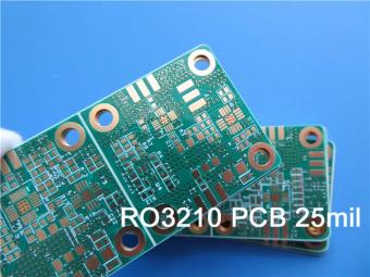
These RO3210 materials are engineered to offer exceptional electrical performance and mechanical stability. RO3210 laminates combine the surface smoothness of a non-woven PTFE laminate.
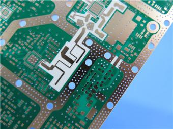
RT/duroid 6035HTC laminates are an exceptional choice for high power applications.
TC350 is designed to provide enhanced heat-transfer through “Best-In-Class” thermal conductivity, while reducing dielectric loss and insertion loss. Lower losses result in higher Amplifier and Antenna Gains/Efficiencies.
RO3035 materials exhibit a coefficient of thermal expansion(CTE) in the X and Y axis of 17 ppm/℃. This expansion coefficient is matched to that of copper, which allows the material to exhibit excellent dimensional stability.
 6-11C Shidai Jingyuan, Fuyong, Baoan, Shenzhen, Guangdong, China 518103


For inquiries about our products or pricelist, please leave to us and we will be in touch within 24 hours.
© Copyright: 2026 Shenzhen Bicheng Electronics Technology Co., Ltd.. All Rights Reserved.

IPv6 network supported


