

 Call Us Now !
Tel : +86 755 27374946
Call Us Now !
Tel : +86 755 27374946
 Order Online Now !
Email : info@bichengpcb.com
Order Online Now !
Email : info@bichengpcb.com
The 2-Layer RO3010 PCB (50mil, EPIG) is a premium high-frequency circuit board designed for engineers who demand stable electrical performance, thermal reliability, and compact form factors.
Item NO.:
BIC-542-v627.0Order(MOQ):
1-10Payment:
T/TProduct Origin:
ChinaShipping Port:
ShenzhenLead Time:
7-10 days
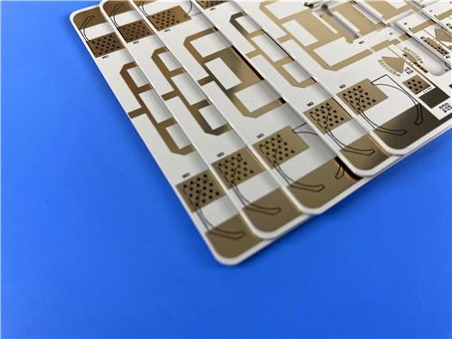
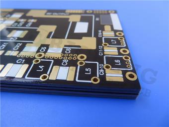
2-Layer Rogers RO3010 PCB DK10.2 50mil 1.27mm Core EPIG Surface Finish Black Silkscreen
PCB Product Introduction
1.1 Product Positioning & Overview
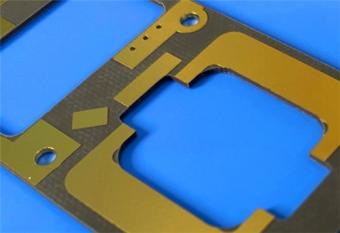
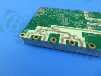
This 2-Layer RO3010 50mil EPIG PCB is a high-performance rigid printed circuit board specially designed for high-frequency, microwave, and RF applications. It is built on Rogers RO3010 ceramic-filled PTFE high-frequency laminate, with a 50mil (1.27mm) dielectric core andnickel-free EPIG surface finish. The Rogers DK10.2 board is manufactured in full compliance with IPC-Class 2 standards, supports stable performance in wide frequency and temperature ranges, and is ideal for automotive radar, satellite antennas, cellular communication systems, wireless patch antennas, and other precision high-frequency modules.
Compared with standard FR-4 PCBs and ordinary microwave substrate boards, thisRogers 3010 PCB features stable dielectric constant, extremely low dissipation factor, excellent thermal expansion matching with copper, outstanding dimensional stability, and strong reliability under lead-free assembly processes. The design removes solder masks on both sides to preserve radio-frequency signal integrity, reduce insertion loss, and avoid parasitic effects caused by additional dielectric layers. The board adopts 1oz outer-layer copper, 20μm via plating thickness, and 100% electrical testing before shipment, ensuring batch consistency, production stability, and long-term performance in real-world operating environments.

1.2 PCB Construction
This table summarizes the complete structural, processing, surface treatment, and quality control specifications of the RO3010 PCB, reflecting high-precision manufacturing for high-frequency applications.
|
Item |
Specification |
|
Base material |
Rogers RO3010 |
|
Layer count |
Double sided (2 layer rigid) |
|
Board dimensions |
89.65 mm × 94.3 mm (1 piece) |
|
Minimum trace / space |
5 / 6 mils |
|
Minimum hole size |
0.25 mm |
|
Blind vias |
None |
|
Finished board thickness |
1.3 mm |
|
Finished copper weight (outer layers) |
1 oz (1.4 mils, 35 μm) |
|
Via plating thickness |
20 μm |
|
Surface finish |
EPIG (nickel free electroless Pd + immersion Au) |
|
Top silkscreen |
Black |
|
Bottom silkscreen |
None |
|
Top solder mask |
None |
|
Bottom solder mask |
None |
|
Pre shipment test |
100% electrical test |
1.3 PCB Stackup
The stackup adopts a symmetrical copper-clad structure with a 50 mil RO3010 core, ensuring impedance consistency, low warpage, and stable high-frequency transmission performance.
|
Layer |
Material |
Thickness |
|
Copper Layer 1 (Top) |
Electrodeposited copper |
35 μm |
|
Core dielectric |
Rogers RO3010 substrate |
50 mil (1.27 mm) |
|
Copper Layer 2 (Bottom) |
Electrodeposited copper |
35 μm |
1.4 PCB Statistics
This table shows the component, pad, via, and net distribution of the board, representing a compact, low-complexity, high-purity RF circuit design.
|
Item |
Quantity |
|
Components |
21 |
|
Total pads |
45 |
|
Through hole pads |
31 |
|
Top SMT pads |
14 |
|
Bottom SMT pads |
0 |
|
Vias |
29 |
|
Nets |
2 |
1.5 PCB Performance Advantages
1.5.1 High-Frequency Signal Integrity
TheRogersboard uses RO3010 high frequency laminate with a dielectric constant of 10.2±0.30 at 10GHz and a dissipation factor of only 0.0022, greatly reducing signal attenuation and ensuring clarity and stability in broadband communication systems.
1.5.2 EPIG Nickel-Free Surface Finish
EPIG (Electroless Palladium Immersion Gold) eliminates the magnetic nickel layer used in traditional ENIG, reducing high-frequency parasitic loss, improving solderability and bonding performance, and supporting long-term reliability in RF modules.
1.5.3 Excellent Thermal & Mechanical Stability
The CTE of RO3010 is highly matched with copper, preventing deformation, delamination, or via cracking during thermal cycling. The decomposition temperature exceeds 500°C, fully compatible with lead-free reflow processes.
1.6 Typical Applications
This RO3010 high frequency PCB is widely used in high-frequency communication and sensing systems, including:
-Automotive radar systems (24GHz, 77–79GHz)
-GPS and global satellite communication antennas
-Cellular telecommunication base station power amplifiers and antennas
-Wireless communication patch antennas
-Direct broadcast satellite equipment
-Cable system data links
-Remote meter reading equipment
-High-performance power backplanes
Conclusion
The 2-Layer RO3010 PCB (50mil, EPIG) is a premium high-frequency circuit board designed for engineers who demand stable electrical performance, thermal reliability, and compact form factors. Its nickel-free EPIG finish, no-solder-mask design, and RO3010 core make it an outstanding choice for automotive radar, satellite communications, and RF power systems.
RO3010 CCL (Copper Clad Laminate) Knowledge
2.1 Basic Definition of CCL
Copper Clad Laminate (CCL) is the core base material of printed circuit boards. It is composed of reinforcing dielectric material and electrolytic or rolled copper foil bonded together under high temperature and pressure. CCL directly determines the electrical performance, thermal stability, mechanical reliability, and service life of PCBs. For high-frequency/RF applications, professional high-frequency CCL (such asceramic-filled PTFE series) must be used to ensure low loss and stable dielectric properties.
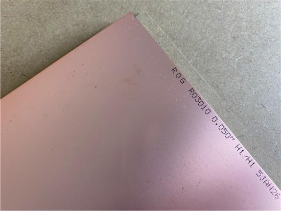
2.2 Introduction to Rogers RO3010 CCL
Rogers RO3010 is a high-performance ceramic-filled PTFE composite CCL belonging to the Rogers RO3000 series. It is designed for commercial microwave and RF applications, providing excellent electrical and mechanical stability at competitive cost. Thehigh DK10.2materialis uniformly filled with ceramic particles to achieve a high dielectric constant while maintaining ultra-low loss, making it ideal for circuit miniaturization and broadband design.

2.3 Key Performance Parameters of RO3010 CCL
|
Property |
Typical Value |
Units |
Test Condition |
Test Method |
|
Dielectric Constant (Process) |
10.2 ± 0.30 |
– |
10 GHz / 23°C |
IPC-TM-650 2.5.5.5 |
|
Dielectric Constant (Design) |
11.2 |
– |
8 – 40 GHz |
Differential Phase Length |
|
Dissipation Factor |
0.0022 |
– |
10 GHz / 23°C |
IPC-TM-650 2.5.5.5 |
|
Thermal Coefficient of Dk |
-395 |
ppm/°C |
-50 to 150°C / 10 GHz |
IPC-TM-650 2.5.5.5 |
|
Volume Resistivity |
10⁵ |
MΩ·cm |
Condition A |
IPC-TM-650 2.5.17.1 |
|
Surface Resistivity |
10⁵ |
MΩ |
Condition A |
IPC-TM-650 2.5.17.1 |
|
Decomposition Temperature (Td) |
>500 |
°C (TGA) |
– |
ASTM D3850 |
|
CTE (X-axis) |
13 |
ppm/°C |
-55 to 288°C |
IPC-TM-650 2.4.41 |
|
CTE (Y-axis) |
11 |
ppm/°C |
-55 to 288°C |
IPC-TM-650 2.4.41 |
|
CTE (Z-axis) |
16 |
ppm/°C |
-55 to 288°C |
IPC-TM-650 2.4.41 |
|
Thermal Conductivity |
0.95 |
W/(m·K) |
50°C |
ASTM D5470 |
|
Copper Peel Strength |
9.4 |
lbs/in |
1 oz ED copper after solder float |
IPC-TM-650 2.4.8 |
|
Young’s Modulus |
1902 (MD), 1934 (CMD) |
MPa |
23°C |
ASTM D638 |
|
Dimensional Stability |
-0.35 (MD), -0.31 (CMD) |
mm/m |
Condition A |
IPC-TM-650 2.2.4 |
|
Flammability |
V-0 |
– |
UL 94 |
UL 94 |
|
Moisture Absorption |
0.05 |
% |
D48/50 |
IPC-TM-650 2.6.2.1 |
|
Density |
2.8 |
g/cm³ |
23°C |
ASTM D792 |
|
Specific Heat Capacity |
0.8 |
J/(g·K) |
– |
Calculated |
|
Lead Free Process Compatible |
Yes |
– |
– |
– |
2.4 Standard Specifications of RO3010 CCL
|
Standard Thicknesses |
Standard Panel Sizes |
Standard Cladding |
|
0.005" (0.13mm) ±0.0005" |
12" x 18" (305 x 457 mm) |
½ oz (18 μm) ED copper |
|
0.010" (0.25mm) ±0.0007" |
24" x 18" (610 x 457 mm) |
1 oz (35 μm) ED copper |
|
0.025" (0.64mm) ±0.0010" |
24" x 21" (610 x 533 mm) |
– |
|
0.050" (1.28mm) ±0.0020" |
– |
– |
2.5 Fabrication Guidelines
RO3010 can be processed using standard PTFE circuit board techniques with minor modifications:
2.6 Core Advantages of RO3010 CCL
1)Stable Dielectric Properties: Stable Dk and low Df over wide frequency and temperature ranges, supporting broadband design.
2)CTE Matched with Copper: Reduces thermal stress, improves reliability of plated through-holes, and enhances dimensional stability.
3)Low Moisture Absorption: Only 0.05%, maintaining stable electrical performance in high-humidity environments.
4)High Thermal Reliability: Td>500°C, compatible with lead-free assembly and harsh thermal environments.
5)Good Process Compatibility: Supports standard PTFE PCB manufacturing processes with minor adjustments.
6)Cost-Effective: Suitable for volume production while maintaining high performance.
2.7 CCL Selection Principles for High-Frequency PCBs


Previous:
2-Layer 15mil Rogers TMM10 RF/Microwave DK9.2 PCB with ENEPIG FinishNext:
RO3003 RF Printed Circuit Board 2-Layer Rogers 3003 60mil 1.524mm PCB Low DK3.0 and Low DF 0.001If you have questions or suggestions,please leave us a message,we will reply you as soon as we can!
Categories
New Products

2-Layer 20mil FSD1020T ENIG High-Frequency PCB with Via Resin Plugged and Capped

4-Layer F4BM265+S1000-2M Material Hyrbid PCB with Blind Via Impedance Control & ENIG

4-Layer Wangling WL-CT338 + FR4 Hybrid PCB ENIG Green Solder Mask White Silkscreen

6-layer Isola 370HR High-Tg FR-4 PCB 2μ" ENIG Impedance Controlled
6-Layer RO4003C + FR4 Mixed Dielectric PCB with Hard Gold Plating Blind Via
30mil Taconic CER-10 2-layer Immersion Silver DK10 High Frequency Laminate PCB
31mil Rogers RT/duroid 5880 Double-sided Bare Copper ENIG Finished PCB
Wangling TFA294 Laminate 40mil Immersion Silver No Solder Mask Silkscreen Custom PCB
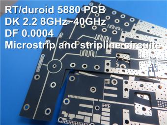
This is a type of double sided RF PCB built on RT/duroid 5880 for the application of Radar Systems.
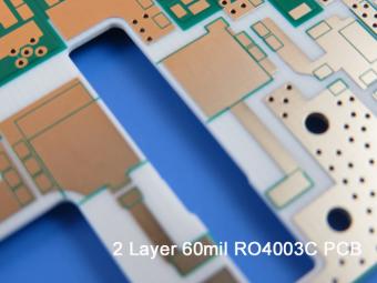
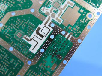
RO4003C PCBs are hydrocarbon ceramic filled laminates, not PTFE which are designed to offer superior high frequency performance.
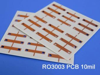
Rogers RO3003 high frequency circuit materials are ceramic-filled PTFE composites intended for use in commercial microwave and RF applications. It was designed to offer exceptional electrical and mechanical stability at competitive prices.
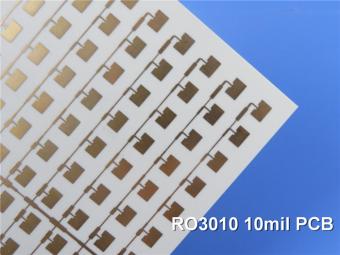
RO3010 laminates are competitively priced products with exceptional mechanical and electrical stability. This stability simplifies the design of broadband components and allows the materials to be used in a wide range of applications over a very broad range of frequencies.
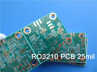
These RO3210 materials are engineered to offer exceptional electrical performance and mechanical stability. RO3210 laminates combine the surface smoothness of a non-woven PTFE laminate.
RT/duroid 6035HTC laminates are an exceptional choice for high power applications.
TC350 is designed to provide enhanced heat-transfer through “Best-In-Class” thermal conductivity, while reducing dielectric loss and insertion loss. Lower losses result in higher Amplifier and Antenna Gains/Efficiencies.
RO3035 materials exhibit a coefficient of thermal expansion(CTE) in the X and Y axis of 17 ppm/℃. This expansion coefficient is matched to that of copper, which allows the material to exhibit excellent dimensional stability.
 6-11C Shidai Jingyuan, Fuyong, Baoan, Shenzhen, Guangdong, China 518103


For inquiries about our products or pricelist, please leave to us and we will be in touch within 24 hours.
© Copyright: 2026 Shenzhen Bicheng Electronics Technology Co., Ltd.. All Rights Reserved.

IPv6 network supported


