

 Call Us Now !
Tel : +86 755 27374946
Call Us Now !
Tel : +86 755 27374946
 Order Online Now !
Email : info@bichengpcb.com
Order Online Now !
Email : info@bichengpcb.com
The F4BTMS220 substrate is a core model within the F4BTMS series, which represents an upgraded iteration of theF4BTM series with pivotal technological breakthroughs in material formulation and manufacturing processes.
Item NO.:
BIC-468-v554.0Order(MOQ):
1-10Payment:
T/TProduct Origin:
ChinaShipping Port:
ShenzhenLead Time:
7-10 days
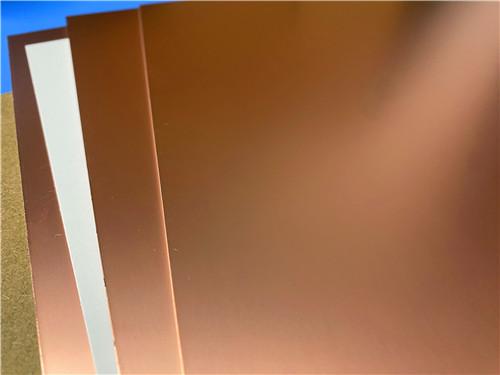
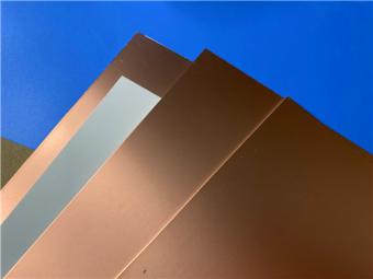
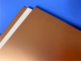
Wangling F4BTMS220 DK2.2 F4B 0.09mm-6.35mm Copper Clad Laminates
The F4BTMS220 substrate is a core model within the F4BTMS series, which represents an upgraded iteration of the F4BTM series with pivotal technological breakthroughs in material formulation and manufacturing processes. This laminate is reinforced with ultra-thin and ultra-fine (quartz) glass fiber cloth, and its material system incorporates a homogeneous mixture of a large quantity of special nano-ceramics and polytetrafluoroethylene (PTFE) resin. This unique composition effectively minimizes the glass fiber effect and dielectric loss during electromagnetic wave propagation, while significantly enhancing dimensional stability, reducing anisotropy in the X/Y/Z directions, and optimizing operating frequency, electrical strength, and thermal conductivity. It also boasts excellent low coefficient of thermal expansion and stable dielectric temperature characteristics.
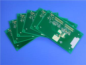
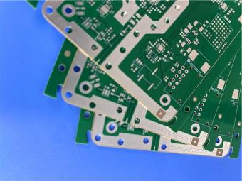
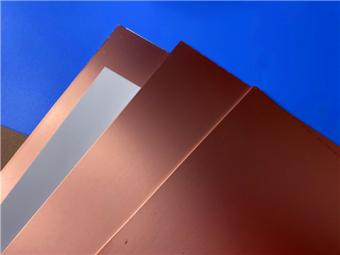
Standard-equipped with RTF low-roughness copper foil, the F4BTMS220 laminate reduces conductor loss while ensuring outstanding peel strength, and can be flexibly paired with copper or aluminum substrates. Circuit board processing can adopt standard PTFE laminate process technology; its superior mechanical and physical properties make it suitable for the fabrication of multi-layer,high-multi-layer PCBs and backplanes, and it also demonstrates excellent processability in scenarios involving dense holes and fine circuits. As an aerospace-grade high-reliability material, the F4BTMS220 Wangling laminate is capable of substituting for comparable foreign-manufactured products, and is widely applied in high-end fields such as aerospace equipment, space and in-cabin devices, microwave/RF equipment, radars (including military radars), feed networks, phase-sensitive antennas, phased array antennas, and satellite communications.
Product Features

Technical Specifications Table
|
Product Characteristic |
Test Condition |
Unit |
F4BTMS220 |
|
Dielectric Constant (Typ.) |
10GHz |
– |
2.2 |
|
Dielectric Constant Tolerance |
– |
– |
±0.02 |
|
Dielectric Constant (Design) |
10GHz |
– |
2.2 |
|
Loss Tangent (Typ.) |
10GHz |
– |
0.0009 |
|
20GHz |
– |
0.001 |
|
|
40GHz |
– |
0.0013 |
|
|
TCDK |
–55℃~150℃ |
ppm/℃ |
–130 |
|
Peel Strength |
1 oz RTF Cu |
N/mm |
>2.4 |
|
Volume Resistivity |
Normal |
MΩ·cm |
≥1×10⁸ |
|
Surface Resistance |
Normal |
MΩ |
≥1×10⁸ |
|
Electric Strength (Z) |
5kV, 500V/s |
kV/mm |
>26 |
|
Breakdown Voltage (XY) |
5kV, 500V/s |
kV |
>35 |
|
CTE (X, Y) |
–55℃~288℃ |
ppm/℃ |
40–50 |
|
CTE (Z) |
–55℃~288℃ |
ppm/℃ |
290 |
|
Thermal Stress |
260℃, 10s, 3 cycles |
– |
No delamination |
|
Water Absorption |
20±2℃, 24h |
% |
0.02 |
|
Density |
Room temp. |
g/cm³ |
2.18 |
|
Long-term Use Temp. |
– |
℃ |
–55~+260 |
|
Thermal Conductivity |
Z-direction |
W/(m·K) |
0.26 |
|
Flammability Rating |
– |
UL-94 |
V-0 |
|
Material Composition |
– |
– |
PTFE, ultra-thin ultra-fine (quartz) glass fiber |
Test Method Notes
The dielectric constant (typical value) is tested in the Z direction of the material, using the strip line method specified in GB/T 12636-1990 or IPC-TM650 2.5.5.5;
Other performance tests are conducted in accordance with or with reference to the test methods specified in IPC-TM-650 or GBT4722-2017;
All test data are typical measurement values, intended to assist customers in material selection. They do not constitute any express or implied warranties, nor do they guarantee that customers will achieve all the performance indicated in this data sheet in specific applications. Customers are responsible for verifying the suitability ofWangling materials in each application.
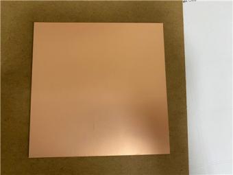
Optional Copper Foil
50Ω Embedded Resistor Copper Foil Description: The resistor film is made of nickel-phosphorus alloy, with a thickness of 0.2 microns and a sheet resistance of 50±5Ωper square centimeter.
AvailableSize
305×460 mm, 460×610 mm, 610×920 mm (custom sizes available)
Dielectric Layer Thickness and Tolerance
Minimum Thickness: 0.09mm;
Available Thicknesses: Products with multiples of 0.09mm or 0.127mm are provided.
|
Thickness (mm) |
Tolerance (mm) |
|
0.09 |
±0.010 |
|
0.127 |
±0.0127 |
|
0.254 |
±0.02 |
|
0.508 |
±0.03 |
|
0.635 |
±0.04 |
|
0.762 |
±0.04 |
|
0.787 |
±0.04 |
|
1.016 |
±0.05 |
|
1.27 |
±0.05 |
|
1.5 |
±0.06 |
|
1.524 |
±0.06 |
|
1.575 |
±0.06 |
|
2.03 |
±0.08 |
|
2.54 |
±0.10 |
|
3.175 |
±0.13 |
|
4.06 |
±0.18 |
|
5.08 |
±0.20 |
|
6.35 |
±0.25 |
Special thicknesses are available through customization; please contact our company for details.
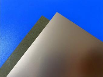
Aluminum/Copper Base Substrates (F4BTMS220-AL / F4BTMS220-CU)
The series can be supplied with aluminum or copper backing for shielding or heat dissipation.
|
Model |
Metal Base |
Specific Gravity |
Thermal Conductivity (W/m·K) |
CTE (ppm/℃) |
Available Metal Thickness (mm) |
Thickness Tolerance (mm) |
Available Size (mm) |
|
F4BTMS220-CU |
Copper |
8.9 |
380 |
17 |
0.48, 0.98, 1.48, 1.98, 2.98, 3.98 (custom available) |
+0.02, –0.05 |
460×610, 460×305 |
|
F4BTMS220-AL |
Aluminum |
2.7 |
180 |
24 |
Same as above |
Same as above |
Same as above |
Electrical Performance Explanation
Frequency variations are based on the median dielectric constant and median loss at 10GHz, while temperature variations are referenced to the median dielectric constant and median loss at room temperature (23℃). These are approximate values of variation trends derived from cumulative data statistics. This explanation aims to illustrate the variation trend of the F4BTMS220 material and does not represent the specific data of each individual product; however, the variation trend of all products is consistent with the following rules:
Excellent frequency stability: Within the frequency range of 0.5~40GHz, the material maintains stable dielectric constant and loss, retaining ultra-low loss values to meet design requirements under different frequencies;
Within the temperature range of -55~150℃, the temperature coefficient of dielectric constant (TCDK) is approximately -130PPM/℃, providing reference data for designs in various temperature environments. The actual usable temperature of the material is far beyond this range.


Previous:
RT/duroid 5880 Copper Clad Laminate 0.127mm 0.252mm 0.508mm 0.787mm 1.575mm SubstrateNext:
F4BME217 F4BME Series 0.2mm-12mm Thick Copper Clad Laminate Reversed RTF Copper FoilIf you have questions or suggestions,please leave us a message,we will reply you as soon as we can!
Categories
New Products

12-layer TG200 TU-872 SLK High-Speed FR4 1.68mm PCB with ENIG Impedance Control

12-Layer RO4350B + RO3010 3.14mm Hybrid PCB Nickel-Free EPIG Surface Finish Blind Via
8-Layer Hybrid PCB RO4003C + S1000-2M FR4 with ENIG Surface Finish Blind Via
6-Layer Isola Astra MT77 PCB with Blind Via & Resin Plug Immersion Silver Finish

2-Layer 20mil FSD1020T ENIG High-Frequency PCB with Via Resin Plugged and Capped

4-Layer F4BM265+S1000-2M Material Hyrbid PCB with Blind Via Impedance Control & ENIG

4-Layer Wangling WL-CT338 + FR4 Hybrid PCB ENIG Green Solder Mask White Silkscreen

6-layer Isola 370HR High-Tg FR-4 PCB 2μ" ENIG Impedance Controlled
RT/duroid 5880LZ PTFE-filled composite materials are engineered for demanding stripline and microstrip circuit applications.

Rogers CuClad 217 is a high-performance printed circuit board (PCB) substrate belonging toRogers Corporation CuClad series, crafted from a composite of woven fiberglass and PTFE (polytetrafluoroethylene).

DiClad 880 Laminate is a high-performance woven fiberglass/PTFE composite laminate designed for use as a printed circuit board substrate.

Wangling F4BM217 is a high-performance PTFE glass cloth copper clad laminate belonging to theF4BM series, developed by Taizhou Wangling Insulation Materials Factory.
The F4BM220 copper clad laminate is a high-performance PTFE glass fiber reinforced copper clad laminate engineered for advanced microwave and RF applications.
Wangling F4BME217 is a high-performance PTFE glass fiber cloth copper-clad laminate developed by Taizhou Wangling Insulation Material Factory.
RT/duroid 5880 is a high-performance laminate constructed from glass microfiber-reinforced PTFE (polytetrafluoroethylene) composite.
TLY-5 Copper clad laminates are produced using ultra-lightweight woven fiberglass, delivering notably higher dimensional stability than chopped fiber-reinforced PTFE composites.
 6-11C Shidai Jingyuan, Fuyong, Baoan, Shenzhen, Guangdong, China 518103


For inquiries about our products or pricelist, please leave to us and we will be in touch within 24 hours.
© Copyright: 2026 Shenzhen Bicheng Electronics Technology Co., Ltd.. All Rights Reserved.

IPv6 network supported


