

 Call Us Now !
Tel : +86 755 27374946
Call Us Now !
Tel : +86 755 27374946
 Order Online Now !
Email : info@bichengpcb.com
Order Online Now !
Email : info@bichengpcb.com
The F4BTMS265 2-Layer ENIG PCB is a purpose-built,high-frequency circuit board that leverages an advanced PTFE/ceramic composite substrate to deliver stable, low-loss electrical performance across a wide temperature range and frequency spectrum.
Item NO.:
BIC-577-v662.0Order(MOQ):
1-10Payment:
T/TProduct Origin:
ChinaShipping Port:
ShenzhenLead Time:
7-10 days
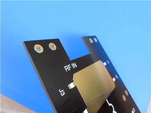
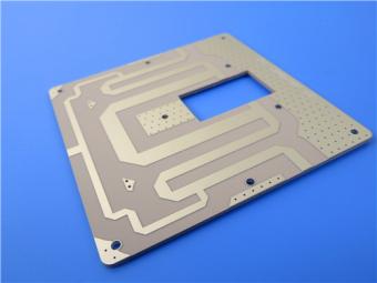
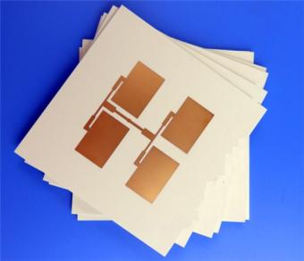
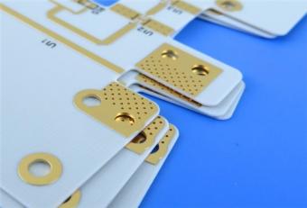
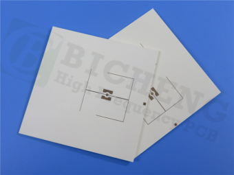
Wangling F4BTMS265 Custom PCB 30mil 2-layer ENIG Black Solder Mask White Silkscreen
1.Overview
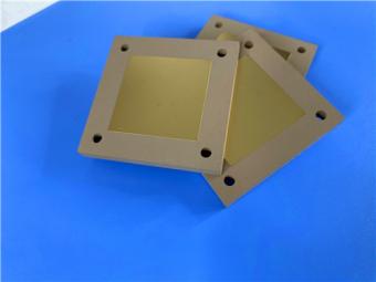
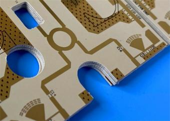
The F4BTMS265 PCB 30mil 2-Layer ENIG is a high-reliability printed circuit board engineered for demanding microwave, RF, and aerospace applications. Built around Taizhou Wangling’s advanced F4BTMS265 ceramic-filled PTFE composite laminate, this2-layer rigid board combines exceptional electrical performance with mechanical robustness.
What sets this F4BTMS265 PCB apart is its substrate: F4BTMS265 is not a conventional PTFE material. It incorporates ultra-thin, ultra-fine glass fiber cloth reinforced with a high loading of uniformly dispersed nano-ceramic fillers. This proprietary formulation minimizes the "fiber effect" on electromagnetic wave propagation, reduces dielectric loss, and significantly improves dimensional stability compared to traditional PTFE laminates. The result is a board that delivers consistent performance from DC up to 40GHz, with a stable dielectric constant of 2.65 at 10GHz and a low dissipation factor of 0.0012 at the same frequency.
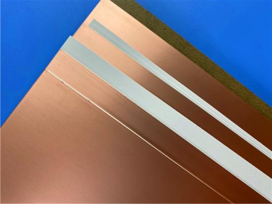
The 30mil Wangling board is manufactured to IPC-Class-2 quality standards, with 100% electrical testing performed prior to shipment. Its 0.85mm finished thickness and 1oz outer layer copper weight strike an optimal balance between mechanical rigidity and electrical performance, making it suitable for both surface-mount and through-hole component integration. The inclusion of RTF (Reverse Treat Foil) low-profile copper foil further reduces conductor loss, a critical advantage for high-frequency designs.
2.PCB Construction Details
The following table summarizes the key manufacturing parameters that define this 30mil F4BTMS265 PCB’s physical and processing characteristics.
|
Parameter |
Specification |
|
Board Dimensions |
97mm × 76mm per panel, ±0.15mm |
|
Minimum Trace/Space |
14/14 mils |
|
Minimum Hole Size |
0.25mm |
|
Blind Vias |
No |
|
Finished Board Thickness |
0.85mm |
|
Finished Copper Weight |
1 oz (1.4 mils) on both outer layers |
|
Via Plating Thickness |
20 μm |
|
Surface Finish |
ENIG (Electroless Nickel Immersion Gold) |
|
Top Silkscreen |
White |
|
Bottom Silkscreen |
No |
|
Top Solder Mask |
Black |
|
Bottom Solder Mask |
No |
|
Electrical Test |
100% prior to shipment |
3.PCB Stackup
The 2-layer stackup is intentionally simple yet carefully optimized for high-frequency signal propagation with controlled impedance and minimal loss.
|
Layer |
Material / Description |
Thickness |
|
Copper Layer 1 (Top) |
1 oz Electro-deposited Copper (RTF) |
35 μm (1.4 mils) |
|
Dielectric Core |
F4BTMS265 |
0.762 mm (30 mils) |
|
Copper Layer 2 (Bottom) |
1 oz Electro-deposited Copper (RTF) |
35 μm (1.4 mils) |
4.PCB Statistics
The following statistical summary provides insight into the design complexity and component density of this PCB.
|
Parameter |
Count |
|
Components |
39 |
|
Total Pads |
67 |
|
Through-Hole Pads |
41 |
|
Top SMT Pads |
26 |
|
Bottom SMT Pads |
0 |
|
Vias |
25 |
|
Nets |
2 |
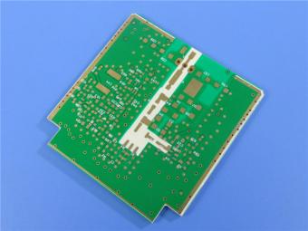
5.Conclusion (PCB Section)
The F4BTMS265 2-Layer ENIG PCB is a purpose-built,high-frequency circuit board that leverages an advanced PTFE/ceramic composite substrate to deliver stable, low-loss electrical performance across a wide temperature range and frequency spectrum. Its conservative yet carefully selected design rules, combined with ENIG surface finish and RTF copper foil, make it an excellent choice for aerospace, radar, and satellite communication applications where reliability and signal fidelity are paramount.
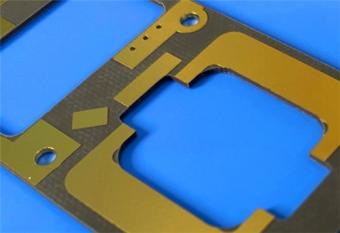
CCL (Copper-Clad Laminate) Deep-Dive: F4BTMS265 Material Knowledge
1.Introduction to F4BTMS Series
The F4BTMS series represents a significant technological advancement over the earlier F4BTM line, developed by Taizhou Wangling Insulation Materials Factory. Through breakthroughs in both material formulation and manufacturing processes, thisF4BTMS substrateseries incorporates a high loading of specially formulated nano-ceramic fillers combined with ultra-thin, ultra-fine glass fiber cloth reinforcement within a polytetrafluoroethylene (PTFE) resin matrix.
This unique combination addresses the inherent limitations of traditional PTFE laminates: the "fiber effect"—where glass fiber weave patterns cause anisotropic dielectric behavior and phase inconsistencies—is minimized due to the ultra-fine fiber structure and homogeneous ceramic distribution. The result is a material with reduced X/Y/Z anisotropy, improved dimensional stability, and a usable frequency range extending well beyond 40GHz.
F4BTMS265 is the specific grade used in this PCB, with a dielectric constant of 2.65 at 10GHz. It is characterized by RTF (Reverse Treat Foil) low-roughness copper foil as standard, which reduces conductor loss while maintaining excellent peel strength. The material is fully compatible with standard PTFE fabrication processes and is available in a wide range of thicknesses, with this F4B DK2.65 PCB utilizing the 0.762mm (30mil) option.
2.F4BTMS265 Material Properties–Complete Datasheet
The following table consolidates all key electrical, thermal, mechanical, and physical properties of F4BTMS265, based on the manufacturer's technical data.
|
Performance Item |
Test Condition |
Unit |
F4BTMS265 Typical Value |
|
Dielectric Constant (Dk, design & typical) |
10GHz |
- |
2.65 |
|
Dk tolerance |
/ |
- |
±0.04 |
|
Dissipation Factor (Df) |
10GHz |
- |
0.0012 |
|
Dissipation Factor (Df) |
20GHz |
- |
0.0014 |
|
Dissipation Factor (Df) |
40GHz |
- |
0.0018 |
|
Dk thermal coefficient |
-55℃ ~ 150℃ |
ppm/℃ |
-88 |
|
Copper peel strength (1oz RTF foil) |
Room temperature |
N/mm |
>1.8 |
|
Volume resistivity |
Ambient |
MΩ·cm |
≥1×10⁸ |
|
Surface resistivity |
Ambient |
MΩ |
≥1×10⁸ |
|
Z-axis electrical strength |
5kV, 500V/s |
kV/mm |
>34 |
|
XY-plane breakdown voltage |
5kV, 500V/s |
kV |
>42 |
|
X-axis CTE |
-55℃ ~ 288℃ |
ppm/℃ |
15 |
|
Y-axis CTE |
-55℃ ~ 288℃ |
ppm/℃ |
20 |
|
Z-axis CTE |
-55℃ ~ 288℃ |
ppm/℃ |
72 |
|
Thermal stress resistance |
260℃, 10s, 3 cycles |
- |
No delamination |
|
Water absorption |
20±2℃, 24h immersion |
% |
0.025 |
|
Material density |
Room temperature |
g/cm³ |
2.26 |
|
Continuous operating temperature |
Thermal cycling chamber |
℃ |
-55 ~ +260 |
|
Z-direction thermal conductivity |
/ |
W/(M·K) |
0.36 |
|
Flame retardancy |
UL standard |
Class |
UL-94 V0 |
|
Core composition |
/ |
- |
PTFE + ultra-fine thin glass cloth + nano ceramic filler |
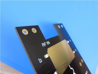
Figure: F4BTMS265 laminate structure showing RTF copper foil, ceramic-filled PTFE dielectric, and ultra-thin glass fabric reinforcement.

3.Key Performance Characteristics Explained
3.1 Electrical Performance
The Dk of 2.65±0.04 at 10GHz is exceptionally stable across production batches, ensuring consistent impedance control—critical for phase-sensitive applications like phased-array antennas. The dissipation factor increases modestly with frequency, from 0.0012 at 10GHz to 0.0018 at 40GHz, demonstrating low dielectric loss even at millimeter-wave frequencies. The negative temperature coefficient of -88 ppm/°C means that as temperature rises, the dielectric constant slightly decreases—a predictable behavior that can be compensated in circuit design, enabling stable phase response across operational temperature ranges.
3.2 Thermal and Mechanical Stability
The CTE values—15 ppm/°C in X-axis, 20 ppm/°C in Y-axis, and 72 ppm/°C in Z-axis—are significantly lower than standard PTFE materials, which typically exhibit CTE >200 ppm/°C in the Z-direction. This low Z-axis CTE is particularly important for plated through-hole reliability, as it minimizes the stress on via barrels during thermal cycling, preventing cracks and open circuits. The material also withstands 260°C thermal stress for 10 seconds over 3 cycles without delamination, confirming its suitability for lead-free soldering processes.
3.3 Environmental and Reliability Factors
With moisture absorption of just 0.025%, F4BTMS265 outperforms many competing PTFE-based laminates, which often absorb 0.05–0.10%. Low moisture absorption translates to stable dielectric properties in humid environments, a key requirement for aerospace and outdoor radar applications. The UL-94 V-0 flammability rating ensures fire safety compliance, while the material's low outgassing characteristics meet space-grade vacuum requirements—an essential attribute for satellite and spaceborne electronics.
3.4 Radiation Resistance and Vacuum Outgassing
F4BTMS265 exhibits excellent radiation resistance, maintaining stable dielectric and mechanical properties after exposure to ionizing radiation doses typical in space environments. Additionally, the material passes stringent vacuum outgassing tests per ASTM E595, with total mass loss (TML) and collected volatile condensable materials (CVCM) well within the limits required for manned and unmanned space missions.
4.Available Thickness Options and Tolerances
F4BTMS265 is available in a wide range of dielectric thicknesses, with the 30mil (0.762mm) option being standard for this PCB. The table below details the full offering, highlighting the tight thickness tolerances maintained across the product line.
|
Thickness (mm) |
Thickness (mil) |
Tolerance (mm) |
Tolerance (mil) |
|
0.127 |
5 |
±0.0127 |
±0.5 |
|
0.254 |
10 |
±0.02 |
±1.0 |
|
0.508 |
20 |
±0.03 |
±1.19 |
|
0.635 |
25 |
±0.04 |
±1.58 |
|
0.762 |
30 |
±0.04 |
±1.58 |
|
0.787 |
30.1 |
±0.04 |
±1.58 |
|
1.016 |
40 |
±0.05 |
±2.0 |
|
1.27 |
50 |
±0.05 |
±2.0 |
|
1.5 |
59 |
±0.06 |
±2.5 |
|
1.524 |
60 |
±0.06 |
±2.5 |
|
1.575 |
62 |
±0.06 |
±2.5 |
|
2.03 |
80 |
±0.08 |
±3.2 |
|
2.54 |
100 |
±0.10 |
±4.0 |
|
3.175 |
125 |
±0.13 |
±5.0 |
|
4.06 |
160 |
±0.18 |
±7.0 |
|
5.08 |
200 |
±0.20 |
±8.0 |
|
6.35 |
250 |
±0.25 |
±10.0 |
Note: Custom thicknesses are available upon request.
5.Copper Foil Options and Metal-Backed Variants
F4BTMS265 is supplied as standard with 1 oz RTF (Reverse Treat Foil) low-roughness copper foil, optimized for high-frequency performance. The foil's reduced surface roughness minimizes the skin effect, lowering conductor losses at microwave and millimeter-wave frequencies. Other copper weights—0.5 oz (0.018mm) and heavier custom options—are available on request.
For applications requiring enhanced thermal dissipation or shielding, Taizhou Wangling offers metal-backed variants:
|
Model |
Metal Base |
Specific Gravity |
Thermal Conductivity (W/m·K) |
CTE (ppm/°C) |
Available Metal Thickness (mm) |
Available Panel Sizes (mm) |
|
F4BTMS265-CU |
Copper (Red/Yellow Brass) |
8.9 |
380 |
17 |
0.48, 0.98, 1.48, 1.98, 2.98, 3.98 (custom others) |
460×610, 460×305 |
|
F4BTMS265-AL |
Aluminum |
2.7 |
180 |
24 |
Same as above |
460×610, 460×305 |
These metal-backed materials are ideal for high-power RF amplifiers and antenna systems where heat spreading and structural rigidity are essential. The model numbering convention is straightforward: F4BTMS265-CU for copper-backed, and F4BTMS265-AL for aluminum-backed laminates.
6.Available Panel Sizes
Standard panel dimensions for F4BTMS265 include:
Custom panel sizes can be accommodated upon consultation.
7.Manufacturing Process Compatibility
Despite its advanced formulation, F4BTMS265 is processable using standard PTFE fabrication techniques—including plasma desmear, controlled-depth routing, and multilayer lamination. Its excellent mechanical properties allow for the production of dense-hole patterns and fine-line geometries, making it suitable for complex multilayer and backplane applications. The material's low Z-axis CTE also contributes to superior plated through-hole reliability, even in demanding thermal cycling environments.
8.Application Scenarios
Based on its properties, F4BTMS265 is specifically recommended for:
|
Application Area |
Specific Use Cases |
|
Aerospace & Space |
Cabin equipment, satellite transceivers, spaceborne radar |
|
Microwave & RF |
Gain blocks, power amplifiers, low-noise front-ends |
|
Radar Systems |
Military radar, phased-array antennas, beamforming networks |
|
Communication Infrastructure |
Feed networks, 5G backhaul, point-to-point microwave links |
|
Test & Measurement |
Calibration fixtures, impedance test coupons, reference standards |
9.Conclusion (CCL Section)
The F4BTMS265 copper clad laminate is a state-of-the-art, ceramic-filled PTFE composite that pushes the boundaries of high-frequency dielectric performance. Its combination of a stable Dk of 2.65, ultra-low dissipation factor across the DC-to-40GHz range, low CTE, minimal moisture absorption, and radiation hardness positions it as a premium choice for aerospace, military, and satellite applications.
The material's RTF copper foil further enhances its high-frequency credentials by reducing conductor losses, while its compatibility with standard processing techniques ensures reliable and cost-effective PCB fabrication. With its comprehensive datasheet, flexible thickness options, and metal-backed variants, F4BTMS265 offers designers a robust and versatile substrate for even the most demanding high-reliability projects.


Previous:
Wangling TFA294 Laminate 40mil Immersion Silver No Solder Mask Silkscreen Custom PCBNext:
8-layer TC350 FR408HR Hybrid PCB with Blind Via Filled and Capped Edge PlatingIf you have questions or suggestions,please leave us a message,we will reply you as soon as we can!
Categories
New Products
30mil Taconic CER-10 2-layer Immersion Silver DK10 High Frequency Laminate PCB
31mil Rogers RT/duroid 5880 Double-sided Bare Copper ENIG Finished PCB
Wangling TFA294 Laminate 40mil Immersion Silver No Solder Mask Silkscreen Custom PCB
50mil TMM6 PCB 2-layer EPIG Rogers DK6.0 Substrate No Solder Mask Silkscreen
60mil TMM10 PCB 1-layer OSP Microwave High Frequency Laminate No Solder Mask
Wangling F4BTMS265 Custom PCB 30mil 2-layer ENIG Black Solder Mask White Silkscreen
RO4835 20mil Rogers Laminate 2-layer Immersion Gold Custom PCB
Rogers 20mil DiClad 527 PCB 2-layer Immersion Gold No Solder Mask Black Silkscreen

RF-10 25mil Taconic PCB Materials stands out as a high-performance solution for RF applications. Its exceptional electrical properties, dimensional stability, thermal conductivity, and adhesion characteristics make it an ideal choice for demanding applications.
The PCB has a 4-layer hybrid stackup with a 0.5oz+plating ground layer, two 1oz ground layers, and a 0.5oz+plating signal layer.
The dimensions of the board are 55.00 x 26.00 mm, with a tolerance of +/- 0.15mm. The board has 16 components, 26 total pads, 9 through-hole pads, 10 top SMT pads, 7 bottom SMT pads, 77 vias, and 82 nets.
Rogers RO4003C PCB is an innovative and advanced circuit board that is made with high-quality materials.
The RO4350B PCB offers a range of benefits that make it an ideal choice for high-frequency applications. Its low dielectric loss and high thermal conductivity make it perfect for high-frequency applications such as RF and microwave circuits.
Bicheng PCB Ships High-Quality PCBs with Shengyi Tg150 ℃ S1000H Material and Advanced Stackup
Rogers RO3010 PCB is ideal for a wide range of high-frequency applications, including power amplifiers, filters, couplers, and antennas.
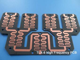
TLX-8 features low dielectric loss, low moisture absorption, and excellent thermal stability, making it ideal for high-frequency and high-speed applications. It has a low dissipation factor, which helps to minimize signal loss and distortion.
 6-11C Shidai Jingyuan, Fuyong, Baoan, Shenzhen, Guangdong, China 518103


For inquiries about our products or pricelist, please leave to us and we will be in touch within 24 hours.
© Copyright: 2026 Shenzhen Bicheng Electronics Technology Co., Ltd.. All Rights Reserved.

IPv6 network supported


