

 Call Us Now !
Tel : +86 755 27374946
Call Us Now !
Tel : +86 755 27374946
 Order Online Now !
Email : info@bichengpcb.com
Order Online Now !
Email : info@bichengpcb.com
This 50mil TMM6 2-layer PCB represents a balanced high-frequency microwave circuit solution that integrates premium Rogers thermoset substrate, low-loss nickel-free EPIG surface treatment and optimized mask-free circuit architecture.
Item NO.:
BIC-579-v664.0Order(MOQ):
1-10Payment:
T/TProduct Origin:
ChinaShipping Port:
ShenzhenLead Time:
7-10 days
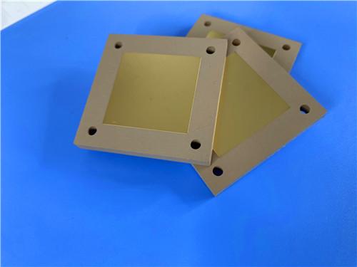
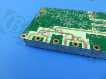
50mil TMM6 PCB 2-layer EPIG Rogers DK6.0 Substrate No Solder Mask Silkscreen
1. Product Overview
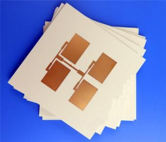
The 50mil TMM6 2-Layer EPIG PCB represents a precision-engineered high-frequency circuit board solution specifically designed for demanding RF and microwave applications. Fabricated using Rogers Corporation's advanced TMM6 thermoset microwave material, this printed circuit board delivers exceptional electrical performance with a stable dielectric constant of 6.0 at 10GHz, making it an ideal choice for applications requiring consistent signal integrity across wide frequency ranges.
This Rogers TMM6 PCB distinguishes itself through its unique combination of ceramic-like electrical properties and the processability of thermoset polymers. Unlike traditional PTFE-based microwave laminates that demand specialized handling techniques, TMM6 enables standard PCB fabrication processes while maintaining superior high-frequency performance. The board's EPIG (Electroless Palladium Immersion Gold, Nickel-free) surface finish further enhances its value proposition by eliminating nickel from the final metallization, thereby reducing signal loss at high frequencies and improving wire bondability—a critical consideration for RF and microwave assemblies where every fraction of a decibel matters.
2. PCB Construction Details
This table systematically summarizes all mechanical, surface treatment and manufacturing tolerance specifications of the finished bare PCB, covering substrate, dimension, circuit feature, plating and surface treatment parameters.
|
Parameter |
Specification |
|
Base Material |
Rogers TMM6 |
|
Layer Count |
2 layers |
|
Board Dimensions |
85.6 mm × 99.75 mm per panel, ±0.15 mm |
|
Minimum Trace / Space |
4 mil / 6 mil (0.102 mm / 0.152 mm) |
|
Minimum Hole Size |
0.35 mm (drilled) |
|
Blind / Buried Vias |
None – all vias are through hole |
|
Finished Board Thickness |
1.35 mm (±10% typical) |
|
Finished Copper Weight (Outer Layers) |
1 oz (1.4 mils / 35 µm) |
|
Via Plating Thickness |
20 µm (minimum) |
|
Surface Finish |
EPIG – Electroless Palladium Immersion Gold (Nickel free) |
|
Top Silkscreen |
No |
|
Bottom Silkscreen |
No |
|
Top Solder Mask |
No |
|
Bottom Solder Mask |
No |
|
Electrical Test |
100% prior to shipment |
3. PCB Stackup Structure
This table clarifies the symmetrical two-layer sandwich structure of the TMM6 PCB, listing each layer material, thickness and functional positioning from top conductive copper to bottom conductive copper.
|
Layer |
Material |
Thickness |
|
Top Copper (Layer 1) |
Electro deposited copper foil |
35 µm (1 oz) |
|
Dielectric Core |
Rogers TMM6 (thermoset, ceramic filled) |
1.27 mm (50 mils) |
|
Bottom Copper (Layer 2) |
Electro deposited copper foil |
35 µm (1 oz) |
4. PCB Circuit Statistical Parameters
This table quantifies all circuit element quantities of the finished PCB, reflecting simple two-net circuit layout characteristics, suitable for compact RF signal transmission modules with limited component count.
|
Parameter |
Value |
|
Components |
23 |
|
Total Pads |
41 |
|
Through-Hole Pads |
25 |
|
Top Side SMT Pads |
16 |
|
Bottom Side SMT Pads |
0 |
|
Vias |
6 (all plated through-hole) |
|
Nets |
2 |
5. Core Differentiated Advantages of This TMM6 EPIG PCB
5.1 Material Differentiation: TMM6 Thermoset Substrate vs PTFE & FR-4
Traditional PTFE microwave laminates require complex sodium napthanate activation before electroless plating, while FR-4 exhibits high Df (dissipation factor) and unstable Dk under temperature variation.Rogers TMM6 is a ceramic-hydrocarbon thermoset composite, combining ceramic substrate’s low-loss stability and standard PCB processing compatibility. Its Dk = 6.0±0.08 at 10GHz enables circuit miniaturization compared to low-DkTMM3/TMM4 series, ideal for compact antenna and filter designs. Thermal coefficient of Dk reaches only -11 ppm/°K, delivering near-constant impedance across -55°C ~ +125°C operating temperature range, eliminating frequency drift caused by ambient temperature change in satellite communication equipment. X/Y axis CTE of 18 ppm/K perfectly matches copper foil’s thermal expansion rate, minimizing via crack and pad delamination risk during lead-free reflow soldering.
5.2 Surface Finish Differentiation: Nickel-Free EPIG vs ENIG/ENEPIG
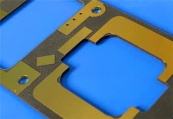
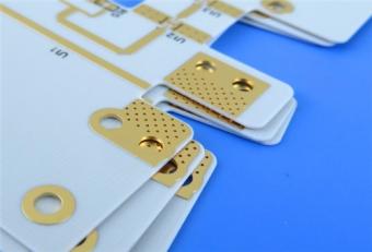
Most high-frequency PCBs adopt ENIG/ENEPIG with thick nickel barrier layers, which introduce ferromagnetic metal loss and severe skin effect attenuation at microwave frequencies above 6GHz. EPIG replaces nickel with ultra-thin electroless palladium (0.10–0.15μm) + immersion gold (0.05–0.1μm), fully nickel-free. Two core performance upgrades: First, drastically suppressed PIM distortion under high RF power, critical for base station combiners and power amplifiers; second, lower high-frequency insertion loss, verified to reduce signal attenuation by approximately 0.2dB/in at 10GHz compared to ENIG finish. Meanwhile, EPIG retains reliable solderability for SAC305 lead-free solder and supports gold wire bonding without pad lifting, matching TMM6’s thermoset wire-bond compatibility.
5.3 Manufacturing Process Optimization for Microwave Performance
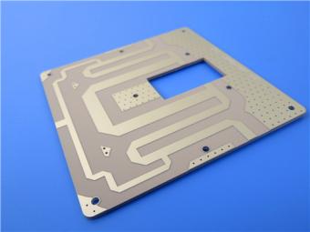
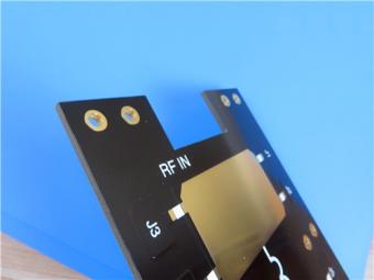
The board cancels top/bottom solder mask and silkscreen layers intentionally. Solder mask dielectric coating introduces extra parasitic capacitance and signal loss at high frequency; removing these layers ensures direct contact between air medium and copper traces to preserve designed impedance accuracy. 4/6 mil fine line geometry supports compact microstrip layout, while 100% electrical testing eliminates open/short circuit defects before delivery. IPC-Class-2 standard balances manufacturing cost and long-term service reliability, fitting industrial communication, test instrument and navigation equipment with extended service life requirements.
5.4 Mechanical & Thermal Stability
TMM6 substrate features decomposition temperature Td = 425°C, fully compatible with multiple lead-free reflow cycles without substrate degradation. Thermal conductivity of 0.72 W/mK is twice that of standard PTFE ceramic laminates, improving heat dissipation of power amplifier circuits to avoid thermal-induced frequency shift. Material resists creep and cold flow deformation, maintaining dimensional stability during long-term equipment operation; chemical resistance to PCB etching, stripping and plating solutions reduces fabrication scrap rate compared to soft fluoropolymer substrates.

6. Typical Application Scenarios
This 50mil TMM6 EPIG PCB targets high-frequency RF and microwave industrial segments, covering:
6.1 RF Microwave Circuits: Compact microstrip/stripline signal transmission boards for communication front-end modules
6.2 Power Amplifiers & Signal Combiners: High-power RF amplifier substrates with low PIM EPIG surface
6.3 RF Filters & Directional Couplers: Narrowband filter core boards requiring stable Dk over temperature
6.4 Satellite Communication Systems: L-band signal receiving circuit substrates for ground satellite terminals
6.5 GPS Navigation Patch Antennas: Miniaturized antenna boards leveraging TMM6’s high Dk for size reduction
6.6 Dielectric Polarizers & Microwave Lenses: Precision dielectric waveguide substrates
6.7 Semiconductor Chip Testers: High-frequency test fixture boards with consistent impedance control
7. Conclusion for PCB Product
This 50mil TMM6 2-layer PCB represents a balanced high-frequency microwave circuit solution that integrates premium Rogers thermoset substrate, low-loss nickel-free EPIG surface treatment and optimized mask-free circuit architecture. Supported by quantifiable stackup, construction and circuit statistics data, it addresses three core pain points of traditional microwave PCBs: unstable dielectric constant under temperature fluctuation, excessive high-frequency signal loss from nickel-containing surface finishes, and complicated special manufacturing workflows of PTFE materials.
The product complies with IPC-Class-2 quality norms and undergoes full electrical testing to guarantee consistent batch performance. Its symmetrical double-layer stackup, 1oz uniform copper and 20μm via plating deliver long-term mechanical and electrical reliability for RF power, satellite navigation and test measurement equipment. For engineers pursuing compact circuit size, low PIM interference and standard PCB process compatibility, this TMM6 2-layer board provides a cost-effective, high-stability alternative to high-cost alumina ceramic substrates and hard-to-process PTFE laminates.
Supplementary In-Depth CCL Knowledge: Rogers TMM6 50mil Copper Clad Laminate
1. CCL Basic Definition & Structural Composition
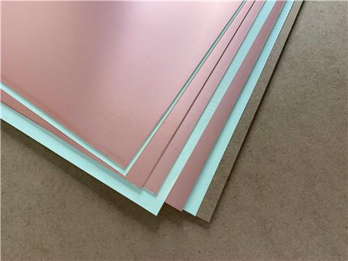
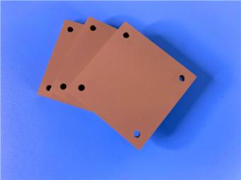
Copper Clad Laminate (CCL) is the fundamental raw substrate for all PCB fabrication, consisting of insulating dielectric core bonded with electrodeposited copper foil on one or both sides via high-temperature thermocompression lamination. The 50mil TMM6 double-sided CCL used for this PCB is a three-layer composite structure: top ED copper foil (35μm), 1.27mm TMM6 ceramic thermoset dielectric core, bottom ED copper foil (35μm). Unlike epoxy FR-4 and fluoropolymer PTFE CCL,TMM6 series belongs to thermoset hydrocarbon ceramic composite CCL, designed exclusively for high-frequency microwave circuit manufacturing, combining the mechanical stability of ceramic substrates and the easy processability of traditional hydrocarbon laminates.
2. Complete TMM6 Electrical, Thermal & Mechanical Property Datasheet Table
|
Performance Category |
Test Item |
TMM6 Typical Value |
Test Direction |
Unit |
Test Condition |
Standard Test Method |
|
Electrical Properties |
Process Dielectric Constant (Dk) |
6.00 ± 0.08 |
Z |
- |
10 GHz |
IPC-TM-650 2.5.5.5 |
|
Design Dielectric Constant |
6.3 |
- |
- |
8–40 GHz |
Differential Phase Length Method |
|
|
Dissipation Factor (Df) |
0.0023 |
Z |
- |
10 GHz |
IPC-TM-650 2.5.5.5 |
|
|
Thermal Coefficient of Dk |
-11 |
- |
ppm/°K |
-55°C ~ +125°C |
IPC-TM-650 2.5.5.5 |
|
|
Insulation Resistance |
>2000 |
- |
GΩ |
C/96/60/95 |
ASTM D257 |
|
|
Volume Resistivity |
1×10⁸ |
- |
MΩ·cm |
Room Temperature |
ASTM D257 |
|
|
Surface Resistivity |
1×10⁹ |
- |
MΩ |
Room Temperature |
ASTM D257 |
|
|
Dielectric Strength |
362 |
Z |
V/mil |
Ambient |
IPC-TM-650 2.5.6.2 |
|
|
Thermal Properties |
Decomposition Temperature (Td) |
425 |
- |
°C |
TGA Heating |
ASTM D3850 |
|
X-axis CTE |
18 |
X |
ppm/K |
0–140°C |
ASTM E831 / IPC-TM-650 2.4.41 |
|
|
Y-axis CTE |
18 |
Y |
ppm/K |
0–140°C |
ASTM E831 / IPC-TM-650 2.4.41 |
|
|
Z-axis CTE |
26 |
Z |
ppm/K |
0–140°C |
ASTM E831 / IPC-TM-650 2.4.41 |
|
|
Thermal Conductivity |
0.72 |
Z |
W/m/K |
80°C |
ASTM C518 |
|
|
Mechanical Properties |
Copper Peel Strength (1oz ED Cu, Post Solder Float) |
5.7 (1.0) |
X/Y |
lb/in (N/mm) |
Lead-Free Reflow |
IPC-TM-650 2.4.8 |
|
Flexural Strength |
15.02 |
X/Y |
kpsi |
Ambient |
ASTM D790 |
|
|
Flexural Modulus |
1.75 |
X/Y |
Mpsi |
Ambient |
ASTM D790 |
|
|
Physical & Environmental |
Moisture Absorption (1.27mm Core) |
0.06 |
- |
% |
D/24/23 |
ASTM D570 |
|
Specific Gravity |
2.37 |
- |
g/cm³ |
Ambient |
ASTM D792 |
|
|
Specific Heat Capacity |
0.78 |
- |
J/g/K |
Calculated |
Theoretical Material Test |
|
|
Compliance |
Lead-Free Process Compatibility |
YES |
- |
- |
- |
- |

3. TMM6 Standard Product Specifications (Thickness, Copper Cladding & Panel Size)
3.1 Standard Core Thickness Range (Tolerance±0.0015 inch):
0.015”, 0.025”, 0.030”, 0.050”, 0.060”, 0.075”, 0.100”, 0.125”, 0.150”, 0.200”, 0.250”, 0.500”;
The PCB in this document adopts 0.050”(50mil / 1.27mm) core.
3.2 Standard Electrodeposited Copper Foil Cladding Options:
½oz (18μm), 1 oz (35μm), 2 oz; this product selects 1oz H1/H1 copper foil.
3.3 Standard Raw Panel Sizes:
18”×12”(457mm×305mm), 18”×24”(457mm×610mm); custom special sizes available on request.
4. TMM6 CCL Core Material Benefits & Mechanism Explanation
4.1 Anti-Creep & Cold Flow Mechanical Stability:
The cross-linked thermoset polymer matrix eliminates permanent deformation under long-term mechanical load, maintaining stable trace geometry during assembly and long-term equipment operation.
4.2 Etchant & Solvent Chemical Resistance:
Resists all standard PCB fabrication chemicals (developers, etchants, strippers), preventing substrate surface corrosion, bubbling or delamination during multi-step manufacturing.
4.3 Reliable Wire Bonding Capability:
Unlike thermoplastic PTFE which softens under heat, TMM6 will not deform at bonding temperature, eliminating pad lifting and enabling stable gold wire bonding for RF chip packages.
4.4 Simplified Plating Process:
No sodium naphthenate surface roughening required before electroless plating, cutting chemical processing steps and reducing substrate surface damage risk.
4.5 Balanced Thermal Dissipation:
Thermal conductivity 0.72W/m/K is double that of conventional PTFE-ceramic laminates, effectively dissipating heat from power amplifier circuits to reduce thermal drift of Dk value.
5. TMM6 CCL Application Matching Logic
TMM6 is positioned as amid-Dk microwave substrate in Rogers TMM product portfolio, filling the gap betweenlow-Dk TMM4 and high-Dk TMM10. Its Dk=6.0 is optimal for compact patch antennas, small-size filters and low-power RF combiners, avoiding the oversized circuit area caused by ultra-low Dk materials and the narrow bandwidth limitation of high-Dk ceramic substrates. Combined with EPIG nickel-free finish, TMM6 CCL becomes the optimal material combination for low-PIM satellite and GPS antenna hardware, which is the core technical differentiation of the50mil 2-layer PCB introduced above.


Previous:
31mil Rogers RT/duroid 5880 Double-sided Bare Copper ENIG Finished PCBNext:
60mil TMM10 PCB 1-layer OSP Microwave High Frequency Laminate No Solder MaskIf you have questions or suggestions,please leave us a message,we will reply you as soon as we can!
Categories
New Products
30mil Taconic CER-10 2-layer Immersion Silver DK10 High Frequency Laminate PCB
31mil Rogers RT/duroid 5880 Double-sided Bare Copper ENIG Finished PCB
Wangling TFA294 Laminate 40mil Immersion Silver No Solder Mask Silkscreen Custom PCB

50mil TMM6 PCB 2-layer EPIG Rogers DK6.0 Substrate No Solder Mask Silkscreen
60mil TMM10 PCB 1-layer OSP Microwave High Frequency Laminate No Solder Mask
Wangling F4BTMS265 Custom PCB 30mil 2-layer ENIG Black Solder Mask White Silkscreen
RO4835 20mil Rogers Laminate 2-layer Immersion Gold Custom PCB
Rogers 20mil DiClad 527 PCB 2-layer Immersion Gold No Solder Mask Black Silkscreen
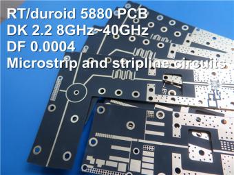
This is a type of double sided RF PCB built on RT/duroid 5880 for the application of Radar Systems.
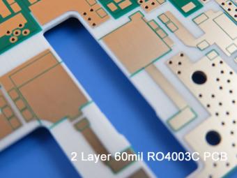
RO4003C PCBs are hydrocarbon ceramic filled laminates, not PTFE which are designed to offer superior high frequency performance.
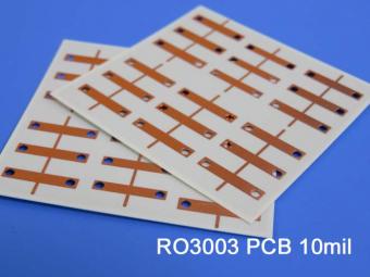
Rogers RO3003 high frequency circuit materials are ceramic-filled PTFE composites intended for use in commercial microwave and RF applications. It was designed to offer exceptional electrical and mechanical stability at competitive prices.
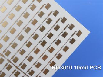
RO3010 laminates are competitively priced products with exceptional mechanical and electrical stability. This stability simplifies the design of broadband components and allows the materials to be used in a wide range of applications over a very broad range of frequencies.
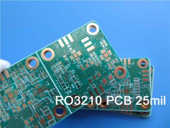
These RO3210 materials are engineered to offer exceptional electrical performance and mechanical stability. RO3210 laminates combine the surface smoothness of a non-woven PTFE laminate.
RT/duroid 6035HTC laminates are an exceptional choice for high power applications.
TC350 is designed to provide enhanced heat-transfer through “Best-In-Class” thermal conductivity, while reducing dielectric loss and insertion loss. Lower losses result in higher Amplifier and Antenna Gains/Efficiencies.
RO3035 materials exhibit a coefficient of thermal expansion(CTE) in the X and Y axis of 17 ppm/℃. This expansion coefficient is matched to that of copper, which allows the material to exhibit excellent dimensional stability.
 6-11C Shidai Jingyuan, Fuyong, Baoan, Shenzhen, Guangdong, China 518103


For inquiries about our products or pricelist, please leave to us and we will be in touch within 24 hours.
© Copyright: 2026 Shenzhen Bicheng Electronics Technology Co., Ltd.. All Rights Reserved.

IPv6 network supported


