

 Call Us Now !
Tel : +86 755 27374946
Call Us Now !
Tel : +86 755 27374946
 Order Online Now !
Email : info@bichengpcb.com
Order Online Now !
Email : info@bichengpcb.com
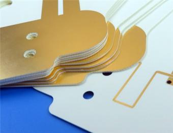
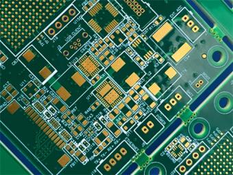
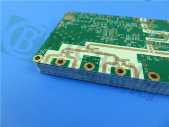
This 20mil RO4835 double-sided RF PCB achieves a balanced combination of stable high-frequency electrical performance, superior thermal oxidation resistance, cost-efficient FR-4 compatible fabrication and reliable immersion gold soldering surface.
Item NO.:
BIC-576-v661.0Order(MOQ):
1-10Payment:
T/TProduct Origin:
ChinaShipping Port:
ShenzhenLead Time:
7-10 days
RO4835 20mil Rogers Laminate 2-layer Immersion Gold Custom PCB
1.Product Overview
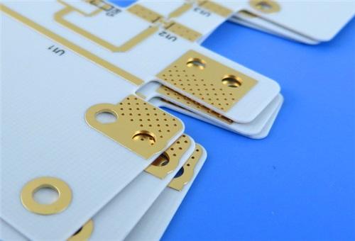
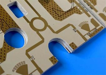
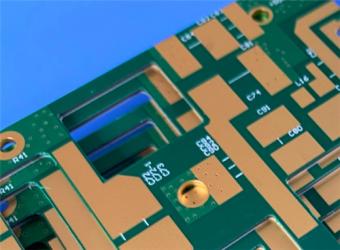
This a custom 2-layer rigid high-frequency PCB built on 20mil Rogers RO4835 hydrocarbon ceramic CCL with immersion gold (ENIG) surface finish. Differentiated from generic FR-4 and standard RO4000-series PCBs, this circuit board targets high-volume, high-temperature RF and automotive radar systems, balancing low-loss microwave performance, outstanding oxidation resistance, FR-4-compatible manufacturability, and reliable immersion gold surface treatment.
All fabrication parameters follow IPC-Class-2 industrial reliability standards, with full electrical continuity testing and strict dimensional tolerance control. The content is split into two independent modules: complete PCB product technical introduction and separate, detailed RO4835 copper-clad laminate material knowledge section.
2. PCB Construction Details
The following table summarizes the key manufacturing specifications of this 20mil RO4835 high-frequency PCB:
|
Parameter |
Specification |
|
Base Material |
RO4835 (Rogers Corporation) |
|
Layer Count |
2 layers |
|
Board Dimensions |
45mm x 83.69mm per panel, ±0.15mm |
|
Minimum Trace/Space |
5/6 mils |
|
Minimum Hole Size |
0.2mm |
|
Via Configuration |
No blind or buried vias (standard through-hole only) |
|
Finished Board Thickness |
0.6mm (20 mils) |
|
Finished Copper Weight |
1 oz (35μm / 1.4 mils) all layers |
|
Via Plating Thickness |
20μm |
|
Surface Finish |
Immersion Gold (ENIG) |
|
Top Silkscreen |
Black |
|
Bottom Silkscreen |
No |
|
Top Solder Mask |
No |
|
Bottom Solder Mask |
No |
|
Silkscreen on Solder Pads |
No |
|
Electrical Testing |
100% Electrical Test |
3. PCB Stackup
The following table details the layer stackup configuration of this 2-layer rigid PCB:
|
Layer |
Material |
Thickness |
|
Layer-1 (Top) |
Finished Copper |
35μm (1 oz / 1.4 mils) |
|
Dielectric |
RO4835 Laminate |
20 mil (0.508mm) |
|
Layer-2 (Bottom) |
Finished Copper |
35μm (1 oz / 1.4 mils) |
4. PCB Statistics
The following table presents the component and pad statistics for this20mil RogersPCB design:
|
Parameter |
Quantity |
|
Components |
18 |
|
Total Pads |
32 |
|
Through-Hole Pads |
24 |
|
Top SMT Pads |
8 |
|
Bottom SMT Pads |
0 |
|
Vias |
9 |
|
Nets |
2 |

5.Core Differentiated Product Advantages
5.1 Substrate Material Unique Performance
Different from traditional FR-4 and standardRO4350B hydrocarbon laminates, RO4835 adds proprietary anti-oxidation fillers in resin formula. Long-term high-temperature aging test data shows that after 1000 hours of 150°C thermal storage, its Dk drift is controlled within±0.02, while ordinary thermoset microwave materials produce Dk deviation exceeding±0.07 under the same condition. This feature guarantees stable radar ranging accuracy for automotive under-hood high-temperature working environments. Meanwhile, Dk=3.48±0.05 and Df=0.0037@10GHz deliver ultra-low signal transmission loss, supporting stable operation from 500MHz up to 77GHz millimeter wave frequency band.
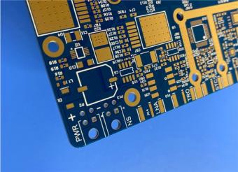
5.2 Immersion Gold Surface Finish Optimization
ENIG surface finish is selected instead of HASL, OSP or hard gold plating to match fine-pitch SMT components. The chemical deposition process forms ultra-flat pad surface without uneven tin height, avoiding soldering failure of small RF chips. The nickel barrier layer blocks copper ion diffusion, and thin gold layer prevents pad oxidation during long-term inventory, extending the PCB shelf life to over 12 months under vacuum packaging. Without solder mask coverage on pads, RF signal transmission loss caused by mask dielectric absorption is completely eliminated, a critical optimization for antenna layout.
5.3 Process & Reliability Control Highlights
No blind/buried vias design: Simplifies manufacturing flow, reduces production defect rate and lowers overall cost for mass-volume automotive radar projects;
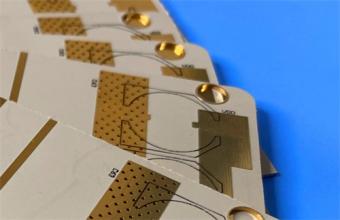
Low 5/6mil minimum trace/space: Supports compact high-density RF wiring without sacrificing impedance control precision;
20μm thick via plating: Matches RO4835 low Z-axis CTE (31ppm/°C), effectively preventing via barrel cracking after repeated lead-free reflow thermal shocks;
Full 100% electrical testing: Every single board passes continuity and insulation resistance inspection, consistent with IPC-Class-2 acceptance criteria for high-reliability RF equipment.
5.4 Target Application Scenarios
This2-layer RO4835 immersion gold PCB is tailor-made for performance-sensitive high-volume RF products, including automotive 24GHz/77GHz radar sensors, point-to-point microwave communication transceivers, RF power amplifier modules, phased array radar antenna units and general discrete RF component carrier boards. Its balanced high-frequency performance and manufacturability make it a cost-effective upgrade solution replacing RO4350B for long-lifetime outdoor and vehicle-mounted electronic systems.
6. Conclusion of PCB Main Body
This20mil RO4835 double-sided RF PCB achieves a balanced combination of stable high-frequency electrical performance, superior thermal oxidation resistance, cost-efficient FR-4 compatible fabrication and reliable immersion gold soldering surface. The standardized two-layer stackup, precise dimensional and circuit geometric specifications. Compared with competing high-frequency PCB products based on PTFE or ordinary hydrocarbon laminates, it stands out via three core differentiation points: enhanced anti-oxidation substrate formula, mask-free bare-copper RF pad design and low-complexity through-via-only construction. It is a mature mass-production PCB solution for automotive radar and millimeter-wave RF equipment, capable of stable worldwide supply and lead-free assembly compatibility.
Appendix: Full Technical Explanation of RO4835 CCL (Copper Clad Laminate)
1. Basic Material Profile of RO4835
Rogers RO4835 is a thermoset hydrocarbon ceramic-filled CCL belonging to Rogers RO4000 series, developed to solve the long-term oxidation drift problem of conventional microwave laminates at elevated temperatures. It retains nearly identical electrical and mechanical parameters as widely recognized RO4350B, while adding proprietary anti-oxidation resin components. Unlike PTFE high-frequency materials, Rogers 4835 supports standard FR-4 manufacturing processes without special sodium etching via treatment, which greatly reduces production threshold and total manufacturing cost for RF PCB factories. It complies with UL 94 V-0 flame retardant standard, RoHS environmental directives and IPC-4103 slash sheet /11 material specification, fully applicable to lead-free SMT reflow processes without blistering or interlayer delamination.
2. Complete RO4835 Material Performance Data Sheet Table
|
Performance Property |
Typical Value |
Test Direction |
Unit |
Test Condition |
Standard Test Method |
|
Process Dielectric Constant (Dk) |
3.48 ±0.05 |
Z axis |
- |
10GHz, 23°C |
IPC-TM-650 2.5.5.5 Clamped Stripline |
|
Design Recommended Dk Value |
3.66 |
Z axis |
- |
8GHz–40GHz |
Differential Phase Length Method |
|
Dissipation Factor (Df, tanδ) |
0.0037 |
Z axis |
- |
10GHz, 23°C |
IPC-TM-650 2.5.5.5 |
|
Thermal Coefficient of Dk |
50 |
Z axis |
ppm/°C |
-100°C ~ 250°C |
IPC-TM-650 2.5.5.5 |
|
Volume Resistivity |
5×10⁸ |
Bulk |
MΩ•cm |
Condition A |
IPC-TM-650 2.5.17.1 |
|
Surface Resistivity |
7×10⁸ |
Surface |
MΩ |
Condition A |
IPC-TM-650 2.5.17.1 |
|
Dielectric Strength |
30.2 (755) |
Z axis |
KV/mm (V/mil) |
Room Temperature |
IPC-TM-650 2.5.6.2 |
|
Tensile Modulus |
7780 (1128) |
Y axis |
MPa (kpsi) |
Room Temperature |
ASTM D638 |
|
Tensile Strength |
136 (19.7) |
Y axis |
MPa (kpsi) |
Room Temperature |
ASTM D638 |
|
Flexural Strength |
186 (27) |
Bulk |
MPa (kpsi) |
Room Temperature |
IPC-TM-650 2.4.4 |
|
Dimensional Stability Post-Etch & 150°C Bake |
<0.5 |
X/Y axis |
mm/m |
Post copper etch + E2 thermal cycle |
IPC-TM-650 2.4.39A |
|
Thermal Expansion Coefficient (CTE) |
2010/12/31 |
X / Y / Z |
ppm/°C |
-55°C ~ 288°C |
IPC-TM-650 2.4.41 |
|
Glass Transition Temperature (Tg) |
>280 |
Bulk |
°C |
TMA Test |
IPC-TM-650 2.4.24.3 |
|
Thermal Decomposition Temp (Td) |
390 |
Bulk |
°C |
TGA Test |
ASTM D3850 |
|
Thermal Conductivity |
0.66 |
Bulk |
W/m/°K |
80°C |
ASTM C518 |
|
Moisture Absorption Rate |
0.05 |
Bulk |
% |
48hrs immersion, 50°C, 0.060” sample |
ASTM D570 |
|
Material Density |
1.92 |
Bulk |
gm/cm³ |
23°C Ambient |
ASTM D792 |
|
1oz Copper Peel Strength Post Solder Float |
0.88 (5.0) |
Copper Interface |
N/mm (pli) |
Standard EDC copper foil |
IPC-TM-650 2.4.8 |
|
Flammability Grade |
V-0 |
- |
- |
Standard thickness laminate |
UL 94 |
|
Lead-Free Process Compatibility |
Yes |
- |
- |
260°C peak reflow |
Industrial Lead-Free Assembly Standard |
3. Core Material Feature & Benefit Interpretation
3.1 Remarkably Enhanced Oxidation Resistance
The core competitive characteristic of RO4835 versus other hydrocarbon thermoset materials. Long-term high-temperature exposure will cause Dk and Df rise of ordinary microwave substrates, which distorts RF signal phase and reduces radar detection precision. RO4835’s modified resin formula slows oxidative degradation rate, maintaining stable dielectric properties over thousands of thermal cycles, perfectly matching automotive long service life requirements.
3.2 Low Loss High-Frequency Electrical Property
Ultra-low dissipation factor 0.0037@10GHz minimizes RF signal energy loss during transmission lines, supporting high operating frequency up to millimeter wave bands, ideal for power amplifiers and phased array antenna systems. Tight Dk tolerance (±0.05) enables accurate impedance control for microstrip and stripline circuits, reducing simulation-to-real measurement deviation.
3.3 Excellent Thermal & Dimensional Stability
Tg exceeds 280°C, covering the full temperature window of PCB lamination, etching, solder mask and lead-free reflow. Low in-plane CTE (10ppm/°C X-axis, 12ppm/°C Y-axis) prevents board warpage during processing; low Z-axis CTE (31ppm/°C) eliminates plated through-hole barrel cracking under thermal shock, improving interconnection reliability.
3.4 Mass-Production & Cost Advantages
Compatible with standard FR-4 production lines without special chemical treatment for vias, cutting manufacturing time and extra equipment investment. Available with Rogers proprietary LoPro reverse-treated copper foil option to further lower high-frequency conductor loss, suitable for large-volume automotive radar batch orders with competitive material cost compared with PTFE laminates.
3.5 Additional Reliability Performance
CAF resistance, low moisture absorption rate and UL 94 V-0 flame retardant rating expand its application range to outdoor, vehicle-mounted and power RF equipment with strict safety standards.
4. Standard Specification of RO4835 CCL Raw Material
4.1 Standard Core Thickness
0.17mm (6.6mil), 0.25mm (10mil), 0.51mm (20mil), 0.76mm (30mil), 1.52mm (60mil); non-standard thickness customizable with 0.0033”incremental step.
4.2 Standard Panel Sizes
305×457mm (12”×18”), 610×457mm (24”×18”), 610×915mm (24”×36”), 1219×915mm (48”×36”); customized large panels available upon request.
4.3 Standard Copper Cladding Weight
0.5oz (18μm) HH/HH foil, 1oz (35μm) H1/H1 electrodeposited copper; LoPro low-roughness reverse treated copper foil optional for ultra-low insertion loss demands.
5. Typical CCL Application Matching
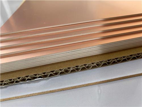
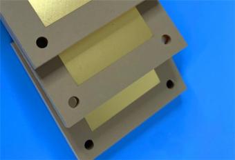
6. Supplementary CCL Material Diagram Description

The physical structure of RO4835 substrate consists of three layers: double-sided electrodeposited copper foil + intermediate hydrocarbon ceramic dielectric core. The ceramic filler uniformly dispersed in hydrocarbon resin balances low dielectric loss and thermal expansion performance; spread glass fiber reinforcement reduces fiber weave effect which causes signal phase distortion at high frequencies. Compared with FR-4’s epoxy resin system, RO4835’s hydrocarbon matrix delivers far lower Df, while its anti-oxidation modification addresses the biggest reliability pain point of traditionalRO4000 series laminatesunder continuous high-temperature operation.


If you have questions or suggestions,please leave us a message,we will reply you as soon as we can!
Categories
New Products

RO4835 20mil Rogers Laminate 2-layer Immersion Gold Custom PCB
Rogers 20mil DiClad 527 PCB 2-layer Immersion Gold No Solder Mask Black Silkscreen
Wangling WL-CT300 5mil Laminate Pure Gold Plating High Frequency PCB
Wangling TF300 25mil DK3.0 Laminate 2-layer PCB Immersion Gold Black Silkscreen
2-Layer 0.5mm TP440 PCB Wangling TP DK4.4 Laminate Immersion Gold
20-Layer Panasonic TU872 HDI PCB ENEPIG 3.0mm Finished Thick Laser-drilled Blind Vias
10-Layer Rogers RO4003C + 370HR FR4 Hybrid Laminate PCB ENIG Impedance Control
8-Layer 10oz Heavy Copper TU-865 Substrate PCB With ENIG Blind &Buried Via
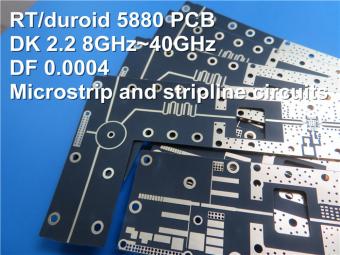
This is a type of double sided RF PCB built on RT/duroid 5880 for the application of Radar Systems.
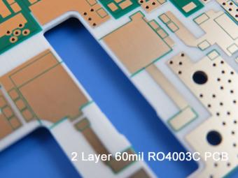
RO4003C PCBs are hydrocarbon ceramic filled laminates, not PTFE which are designed to offer superior high frequency performance.
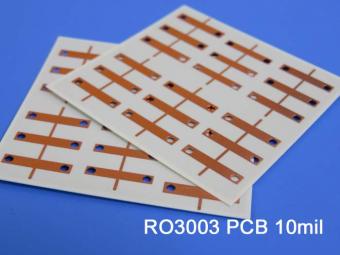
Rogers RO3003 high frequency circuit materials are ceramic-filled PTFE composites intended for use in commercial microwave and RF applications. It was designed to offer exceptional electrical and mechanical stability at competitive prices.
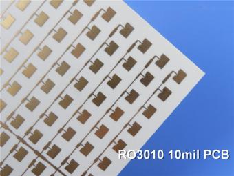
RO3010 laminates are competitively priced products with exceptional mechanical and electrical stability. This stability simplifies the design of broadband components and allows the materials to be used in a wide range of applications over a very broad range of frequencies.
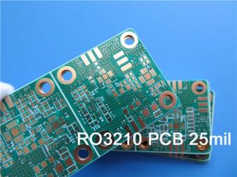
These RO3210 materials are engineered to offer exceptional electrical performance and mechanical stability. RO3210 laminates combine the surface smoothness of a non-woven PTFE laminate.
RT/duroid 6035HTC laminates are an exceptional choice for high power applications.
TC350 is designed to provide enhanced heat-transfer through “Best-In-Class” thermal conductivity, while reducing dielectric loss and insertion loss. Lower losses result in higher Amplifier and Antenna Gains/Efficiencies.
RO3035 materials exhibit a coefficient of thermal expansion(CTE) in the X and Y axis of 17 ppm/℃. This expansion coefficient is matched to that of copper, which allows the material to exhibit excellent dimensional stability.
 6-11C Shidai Jingyuan, Fuyong, Baoan, Shenzhen, Guangdong, China 518103


For inquiries about our products or pricelist, please leave to us and we will be in touch within 24 hours.
© Copyright: 2026 Shenzhen Bicheng Electronics Technology Co., Ltd.. All Rights Reserved.

IPv6 network supported


