

 Call Us Now !
Tel : +86 755 27374946
Call Us Now !
Tel : +86 755 27374946
 Order Online Now !
Email : info@bichengpcb.com
Order Online Now !
Email : info@bichengpcb.com

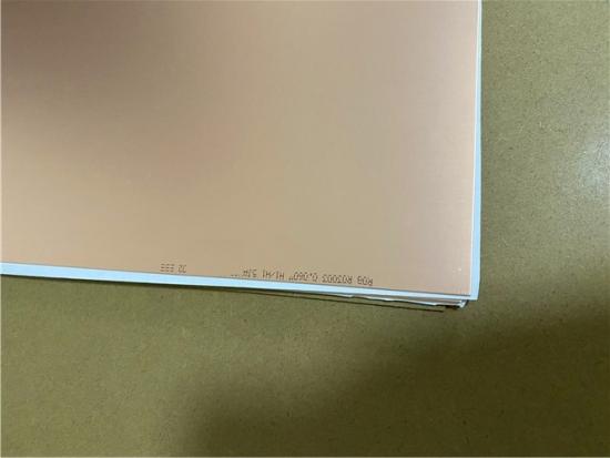
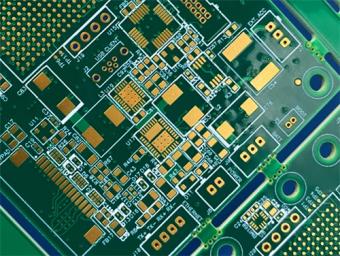
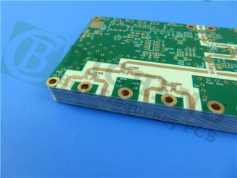
This 20mil DiClad 527 2-layer immersion gold PCB represents a carefully engineered solution for high-frequency applications where signal integrity, dimensional stability, and low loss are non-negotiable requirements.
Item NO.:
BIC-575-v660.0Order(MOQ):
1-10Payment:
T/TProduct Origin:
ChinaShipping Port:
ShenzhenLead Time:
7-10 days
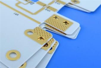
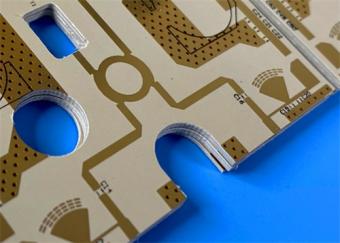
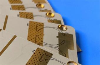
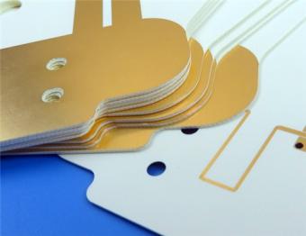
Rogers 20mil DiClad 527 PCB 2-layer Immersion Gold No Solder Mask Black Silkscreen
1. Product Overview
This product is a rigid double-sided high-frequency printed circuit board built on Rogers DiClad 527 woven fiberglass-reinforced PTFE substrate with a 0.508mm (20mil) core dielectric, finished with electroless nickel immersion gold (ENIG) surface treatment. Tailored for RF, microwave, and phased array industrial applications, this DiClad 527 PCB strikes a balanced performance tradeoff between ultra-low high-frequency signal loss, superior dimensional stability, and manufacturability—differentiating it from standard FR-4, low-fiberglass PTFE laminates, and entry-level microwave PCBs.
Unlike conventional high-PTFE microwave substrates prone to thermal creep and dimensional shift during multi-step fabrication, Rogers DiClad 527’s elevated fiberglass-to-PTFE ratio delivers mechanical rigidity close to traditional circuit materials while retaining the stable low-loss electrical properties required for 1 MHz to 30 GHz broadband operation. The 2-layer simple stackup eliminates complex interlayer registration risks, while immersion gold surface finish guarantees flat solder pads for SMT component assembly, consistent contact resistance, and long-term oxidation resistance. All production processes comply with IPC-Class-2 industrial reliability standards, with 100% full electrical continuity and isolation testing implemented before shipment to eliminate open/short circuit defects.
This technical brief systematically breaks down the 20mil DiClad 527 PCB’s construction, stackup, circuit layout statistics, manufacturing specifications, performance differentiation, and applicable end markets, followed by a standalone comprehensive technical deep dive into the DiClad 527 copper-clad laminate (CCL) base material with full datasheet tables, frequency characteristic charts, and material mechanism analysis.

2. PCB Construction Details
The following table summarizes the core construction parameters that define this PCB’s physical and manufacturing specifications.
|
Parameter |
Specification |
|
Base Material |
Rogers DiClad 527 (PTFE/Woven Fiberglass) |
|
Layer Count |
2-layer rigid |
|
Board Dimensions |
49.63mm × 91.54mm per panel, ±0.15mm |
|
Finished Board Thickness |
0.6mm |
|
Minimum Trace/Space |
4/6 mils |
|
Minimum Hole Size |
0.3mm |
|
Via Type |
Through-hole only (no blind vias) |
|
Via Plating Thickness |
20 μm |
|
Finished Copper Weight |
1 oz (35 μm / 1.4 mils) outer layers |
|
Surface Finish |
Immersion Gold (ENIG – Electroless Nickel Immersion Gold) |
|
Top Silkscreen |
Black |
|
Bottom Silkscreen |
None |
|
Top Solder Mask |
None |
|
Bottom Solder Mask |
None |
|
Electrical Test |
100% prior to shipment |
3. PCB Stackup
The layer stackup defines the vertical construction of the board, with copper layers symmetrically arranged around theDiClad 527 dielectric core.
|
Layer |
Material |
Thickness |
|
Top Copper (Layer 1) |
Electro-deposited Copper |
35 μm (1 oz) |
|
Dielectric Core |
DiClad 527 (PTFE/Woven Fiberglass) |
0.508 mm (20 mil) |
|
Bottom Copper (Layer 2) |
Electro-deposited Copper |
35 μm (1 oz) |
4. PCB Statistics
The following statistics quantify the board’s complexity, component density, and interconnect architecture.
|
Metric |
Value |
|
Components |
36 |
|
Total Pads |
104 |
|
Through-Hole Pads |
63 |
|
Top SMT Pads |
41 |
|
Bottom SMT Pads |
0 |
|
Vias |
19 |
|
Nets |
2 |
5. Design Features and Differentiating Attributes
5.1 The DiClad 527 Advantage
What distinguishes this PCB from conventional high-frequency boards is its foundation on DiClad 527. Unlike non-woven PTFE-based laminates, DiClad 527 employs precision-woven fiberglass reinforcement. This woven structure provides far greater dimensional stability than non-woven alternatives, minimizing substrate movement during thermal cycles and lamination processes. The controlled, cloth-based construction also ensures excellent dielectric constant uniformity across the entire panel—a critical factor for the consistent performance of sensitive components like filters, couplers, and low-noise amplifiers.
5.2 Immersion Gold (ENIG) Surface Finish
The immersion gold finish (Electroless Nickel Immersion Gold) provides several key advantages for this high-frequency application:
6. Application Suitability
The combination of DiClad 527’s electrical properties and this 20mil Rogers PCB’s precision fabrication makes it suitable for a range of demanding high-frequency applications:
7. Conclusion
This 20mil DiClad 527 2-layer immersion gold PCB represents a carefully engineered solution for high-frequency applications where signal integrity, dimensional stability, and low loss are non-negotiable requirements. Built on Rogers’precision-woven fiberglass/PTFE composite, the board delivers dielectric constant stability of 2.40–2.60 across frequency, a dissipation factor of just 0.0017 at 10 GHz, and exceptional dimensional stability with X/Y CTE of 14/21 ppm/°C. The 1oz copper layers, 20μm via plating, and ENIG surface finish ensure robust electrical and mechanical performance, while the IPC-Class-2 fabrication standard and 100% electrical testing guarantee quality and reliability.
For engineers designing RF and microwave circuits that demand consistent, predictable performance across temperature, frequency, and environmental conditions, this DiClad 527 high frequency PCB offers a proven foundation that balances the low-loss advantages of PTFE with the mechanical robustness of woven fiberglass reinforcement.
CCL Knowledge Base: Rogers DiClad 527 Laminate
1. Material Overview
Rogers DiClad 527 laminates are woven fiberglass-reinforced PTFE (polytetrafluoroethylene) composite materials engineered for use as high-performance printed circuit board substrates. The DiClad series represents a family of laminates where precise control of the fiberglass-to-PTFE ratio enables a range of dielectric constant choices—from the lowest Dk and dissipation factor to more highly reinforced laminates with superior dimensional stability.
DiClad 527 substrate specifically employs a higher fiberglass reinforcement ratio than many other PTFE-based laminates. This carefully controlled ratio provides a higher dielectric constant range (2.40–2.65) while delivering mechanical properties that approach conventional substrates like FR-4. The woven fiberglass reinforcement offers greater dimensional stability than non-woven fiberglass reinforced PTFE laminates of similar dielectric constants, while the coated fiberglass plies in DiClad materials are aligned in the same direction.
1.1 Key Features
1.2 Key Benefits

2. Standard Offerings
Rogers offers DiClad 527 in the following standard configurations:
|
Standard Thicknesses |
Standard Panel Sizes |
Standard Claddings |
|
0.020" (0.508mm) ± 0.0020" |
12" × 18" (305 × 457mm) |
Electrodeposited Copper Foil: ½ oz (18μm) |
|
0.030" (0.762mm) ± 0.0020" |
18" × 12" (457 × 305mm) |
Electrodeposited Copper Foil: 1 oz (35μm) |
|
0.060" (1.524mm) ± 0.0020" |
18" × 24" (457 × 610mm) |
|
|
24" × 18" (610 × 457mm) |
|
|
The 0.020" (0.508mm) thickness used in this PCB represents the thinnest standard offering, enabling compact, lightweight designs while maintaining the material’s full electrical and mechanical property set.
3. Complete Properties Table
The following comprehensive table presents all key properties of DiClad 527 laminate as specified in Rogers’official data sheet, with test conditions and methods.
|
Property |
DiClad 527 Typical Value |
Units |
Test Conditions |
Test Method |
|
Electrical Properties |
||||
|
Dielectric Constant |
2.40–2.60 |
— |
23°C @ 50% RH, 10 GHz |
IPC TM-650 2.5.5.5 |
|
Dielectric Constant |
2.40–2.60 |
— |
23°C @ 50% RH, 1 MHz |
IPC TM-650 2.5.5.3 |
|
Dissipation Factor |
0.0017 |
— |
23°C @ 50% RH, 10 GHz |
IPC TM-650 2.5.5.5 |
|
Dissipation Factor |
0.001 |
— |
23°C @ 50% RH, 1 MHz |
IPC TM-650 2.5.5.3 |
|
Thermal Coefficient of Dk (TcDK) |
-153 |
ppm/°C |
-10°C to 140°C, 10 GHz |
IPC TM-650 2.5.5.5 |
|
Volume Resistivity |
1.2 × 10⁹ |
MΩ-cm |
C96/35/90 |
IPC TM-650 2.5.17.1 |
|
Surface Resistivity |
4.5 × 10⁷ |
MΩ |
C96/35/90 |
IPC TM-650 2.5.17.1 |
|
Dielectric Breakdown |
>45 |
kV |
D48/50 |
ASTM D-149 |
|
Arc Resistance |
>180 |
seconds |
— |
ASTM D-495 |
|
Thermal Properties |
|
|
|
|
|
CTE – X Axis |
14 |
ppm/°C |
50°C to 150°C |
IPC TM-650 2.4.41 |
|
CTE – Y Axis |
21 |
ppm/°C |
50°C to 150°C |
IPC TM-650 2.4.41 |
|
CTE – Z Axis |
173 |
ppm/°C |
50°C to 150°C |
IPC TM-650 2.4.24 |
|
Thermal Conductivity |
0.26 |
W/(m·K) |
— |
ASTM E1461 |
|
Mechanical Properties |
||||
|
Copper Peel Strength |
14 |
lbs/in |
10s @ 288°C, 35 μm foil |
IPC TM-650 2.4.8 |
|
Young’s Modulus (MD, CMD) |
517, 706 |
kpsi |
23°C @ 50% RH |
ASTM D-638 |
|
Tensile Strength (MD, CMD) |
19.0, 15.0 |
kpsi |
23°C @ 50% RH |
ASTM D-882 |
|
Compressive Modulus |
359 |
kpsi |
23°C @ 50% RH |
ASTM D-695 |
|
Flexural Modulus |
537 |
kpsi |
23°C @ 50% RH |
ASTM D-3039 |
|
Physical & Other Properties |
||||
|
Flammability |
V-0 |
— |
C48/23/50 & C168/70 |
UL 94 |
|
Moisture Absorption |
0.03 |
% |
E1/105+D24/23 |
IPC TM-650 2.6.2.2 |
|
Density |
2.31 |
g/cm³ |
C24/23/50, Method A |
ASTM D792 |
|
NASA Outgassing |
||||
|
Total Mass Loss (TML) |
0.02 |
% |
125°C, ≤10⁻⁶ torr |
NASA SP-R-0022A |
|
Collected Volatile Condensable Material (CVCM) |
0 |
% |
125°C, ≤10⁻⁶ torr |
NASA SP-R-0022A |
|
Water Vapor Recovered (WVR) |
0.01 |
% |
125°C, ≤10⁻⁶ torr |
NASA SP-R-0022A |
Note: Typical values are representations of average values for the population of the property. For specification values, contact Rogers Corporation.
4. Frequency Stability Characteristics
DiClad 527 material exhibits exceptional stability of dielectric constant and dissipation factor across frequency. This characteristic, demonstrated through free-space and circular resonator cavity measurements, highlights the inherent robustness of Rogers’laminates across the electromagnetic spectrum. The stability of Dk over frequency simplifies the final design process when working across the EM spectrum and ensures easy design transition and scalability. Similarly, the stability of dissipation factor across frequency provides a stable platform for high-frequency applications where signal integrity is critical to overall system performance.
This frequency stability is a key differentiator from many competing PTFE-based substrates, where Dk and loss tangent can vary significantly with frequency, complicating wideband design and requiring extensive characterization.


Previous:
RO4835 20mil Rogers Laminate 2-layer Immersion Gold Custom PCBNext:
2-Layer RT/duroid 6006 PCB 10mil Rogers Substrate Immersion Silver No Solder MaskIf you have questions or suggestions,please leave us a message,we will reply you as soon as we can!
Categories
New Products
RO4835 20mil Rogers Laminate 2-layer Immersion Gold Custom PCB
Rogers 20mil DiClad 527 PCB 2-layer Immersion Gold No Solder Mask Black Silkscreen
Wangling WL-CT300 5mil Laminate Pure Gold Plating High Frequency PCB
Wangling TF300 25mil DK3.0 Laminate 2-layer PCB Immersion Gold Black Silkscreen
2-Layer 0.5mm TP440 PCB Wangling TP DK4.4 Laminate Immersion Gold
20-Layer Panasonic TU872 HDI PCB ENEPIG 3.0mm Finished Thick Laser-drilled Blind Vias
10-Layer Rogers RO4003C + 370HR FR4 Hybrid Laminate PCB ENIG Impedance Control
8-Layer 10oz Heavy Copper TU-865 Substrate PCB With ENIG Blind &Buried Via
This is a type of double sided RF PCB built on RT/duroid 5880 for the application of Radar Systems.
RO4003C PCBs are hydrocarbon ceramic filled laminates, not PTFE which are designed to offer superior high frequency performance.
Rogers RO3003 high frequency circuit materials are ceramic-filled PTFE composites intended for use in commercial microwave and RF applications. It was designed to offer exceptional electrical and mechanical stability at competitive prices.
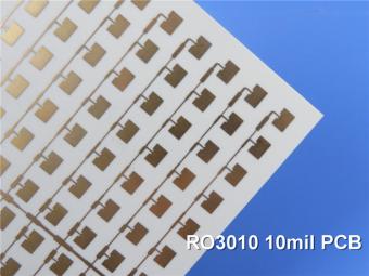
RO3010 laminates are competitively priced products with exceptional mechanical and electrical stability. This stability simplifies the design of broadband components and allows the materials to be used in a wide range of applications over a very broad range of frequencies.
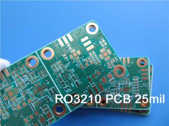
These RO3210 materials are engineered to offer exceptional electrical performance and mechanical stability. RO3210 laminates combine the surface smoothness of a non-woven PTFE laminate.
RT/duroid 6035HTC laminates are an exceptional choice for high power applications.
TC350 is designed to provide enhanced heat-transfer through “Best-In-Class” thermal conductivity, while reducing dielectric loss and insertion loss. Lower losses result in higher Amplifier and Antenna Gains/Efficiencies.
RO3035 materials exhibit a coefficient of thermal expansion(CTE) in the X and Y axis of 17 ppm/℃. This expansion coefficient is matched to that of copper, which allows the material to exhibit excellent dimensional stability.
 6-11C Shidai Jingyuan, Fuyong, Baoan, Shenzhen, Guangdong, China 518103


For inquiries about our products or pricelist, please leave to us and we will be in touch within 24 hours.
© Copyright: 2026 Shenzhen Bicheng Electronics Technology Co., Ltd.. All Rights Reserved.

IPv6 network supported


